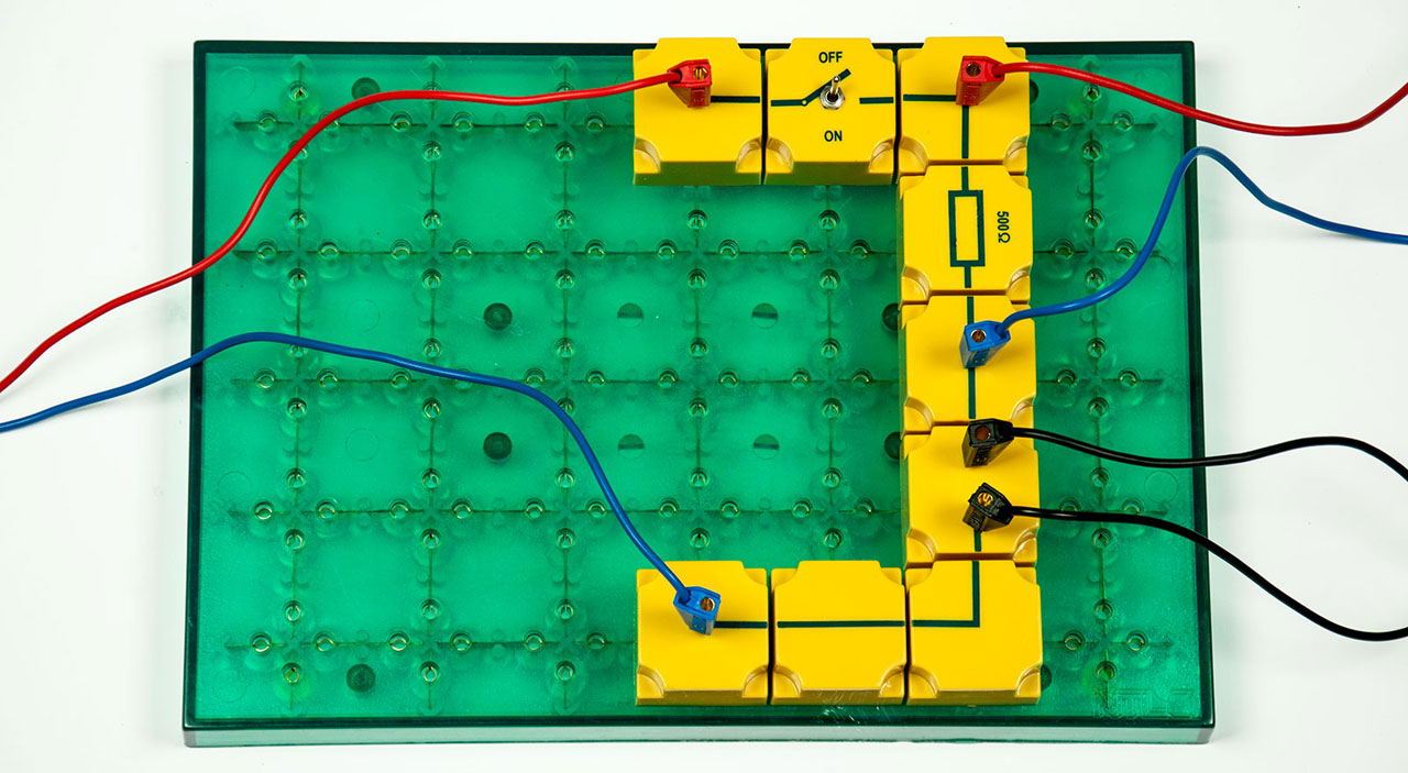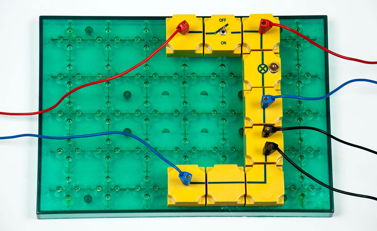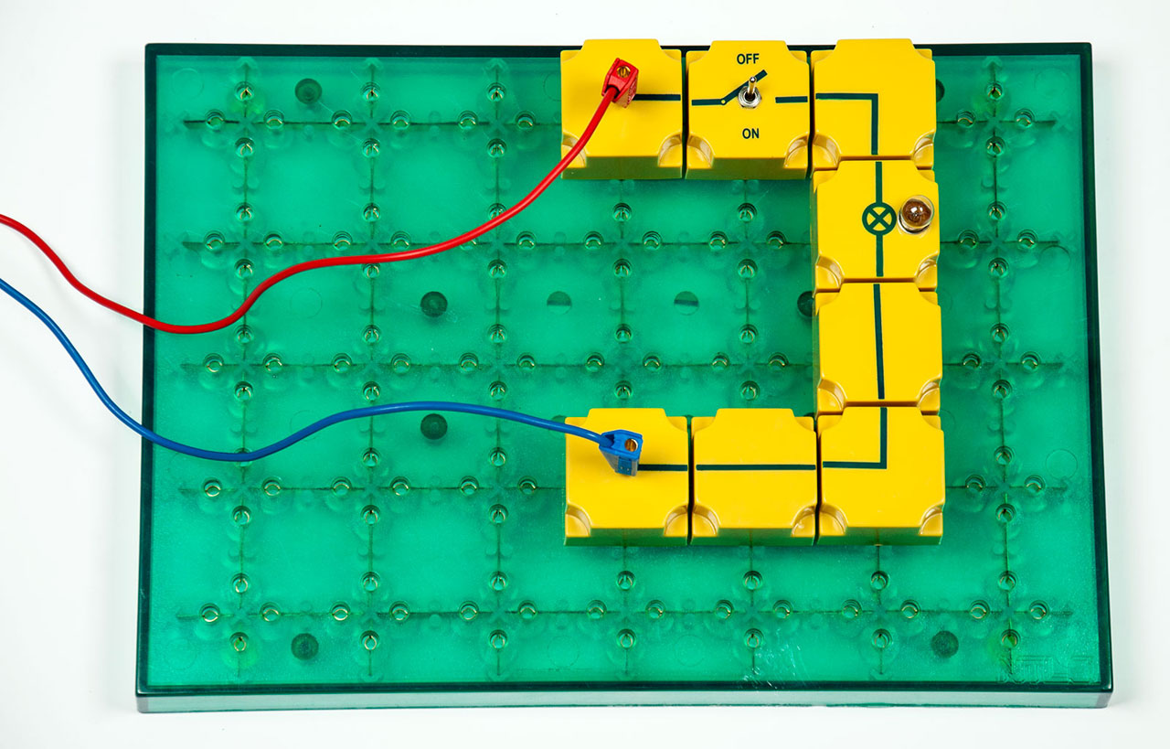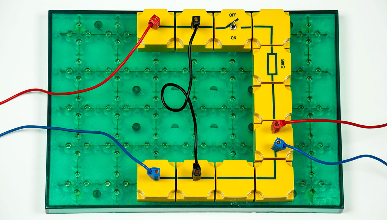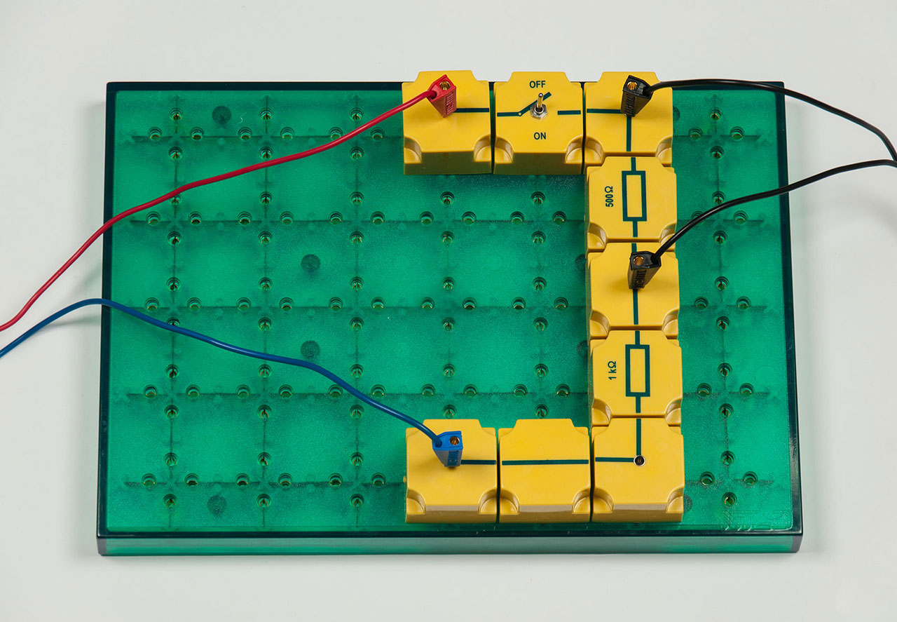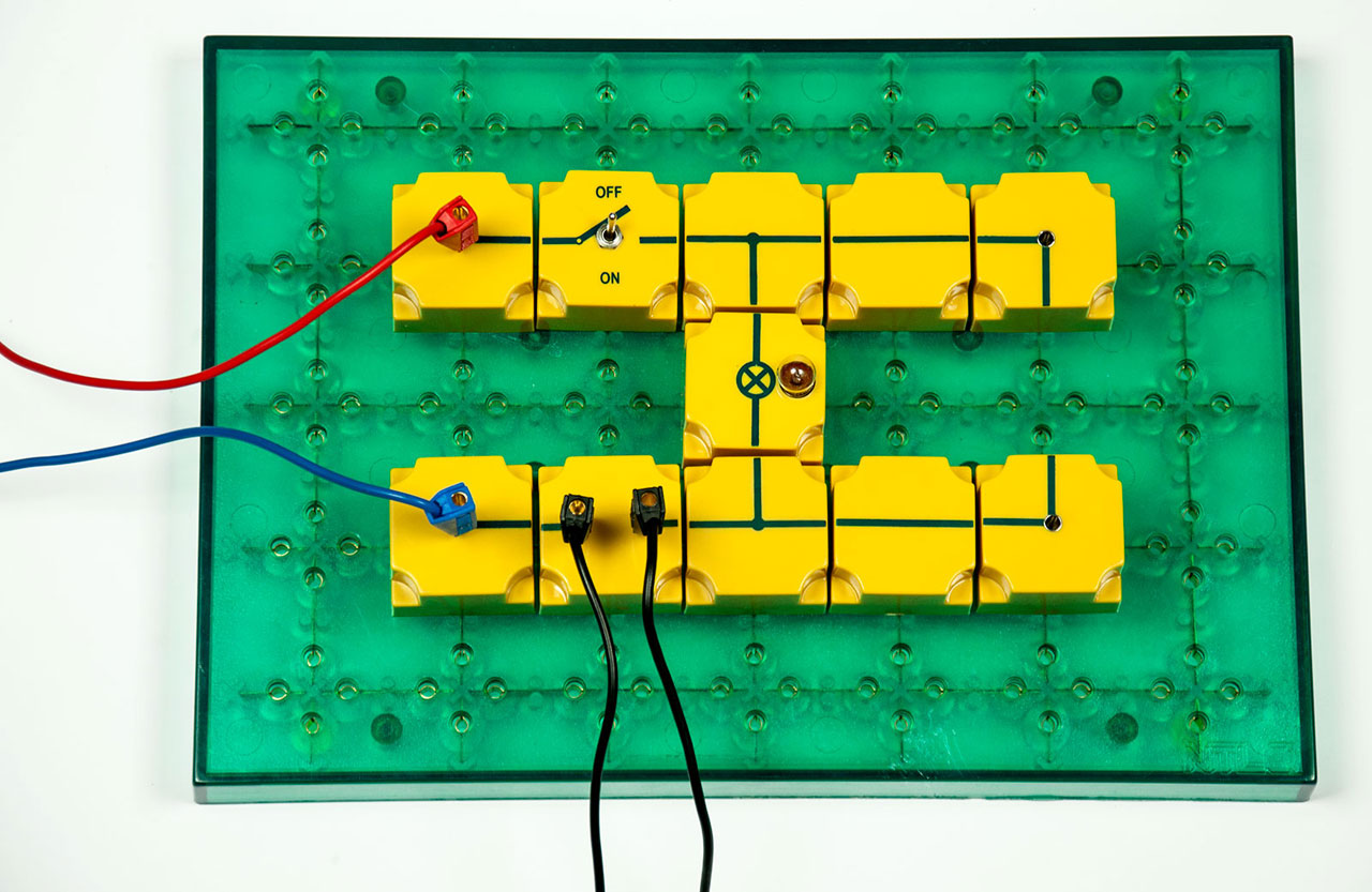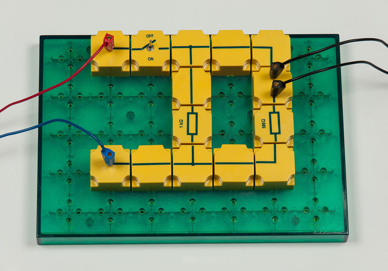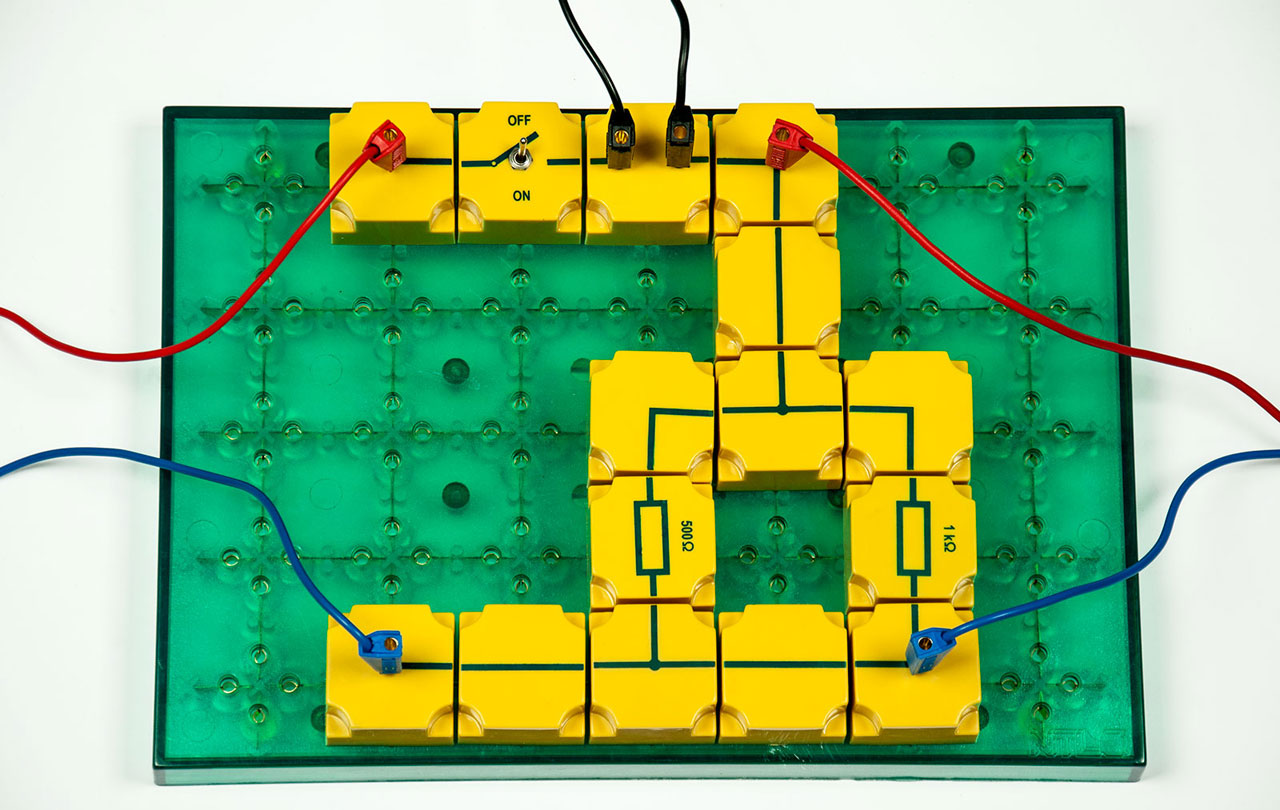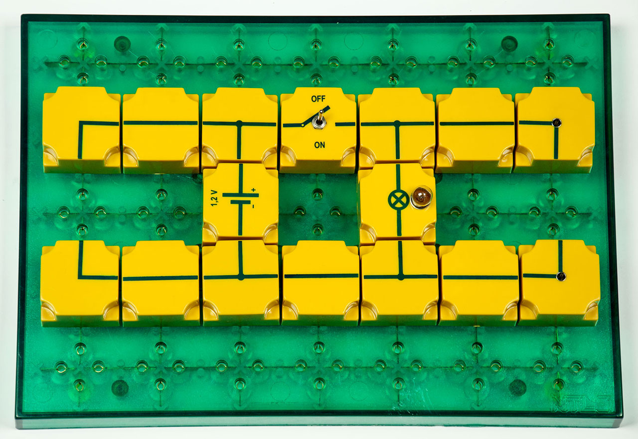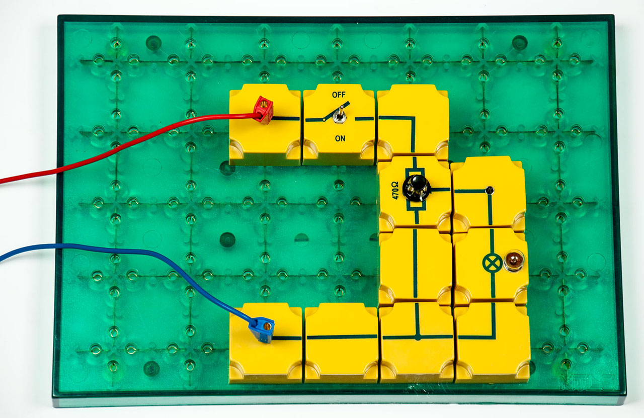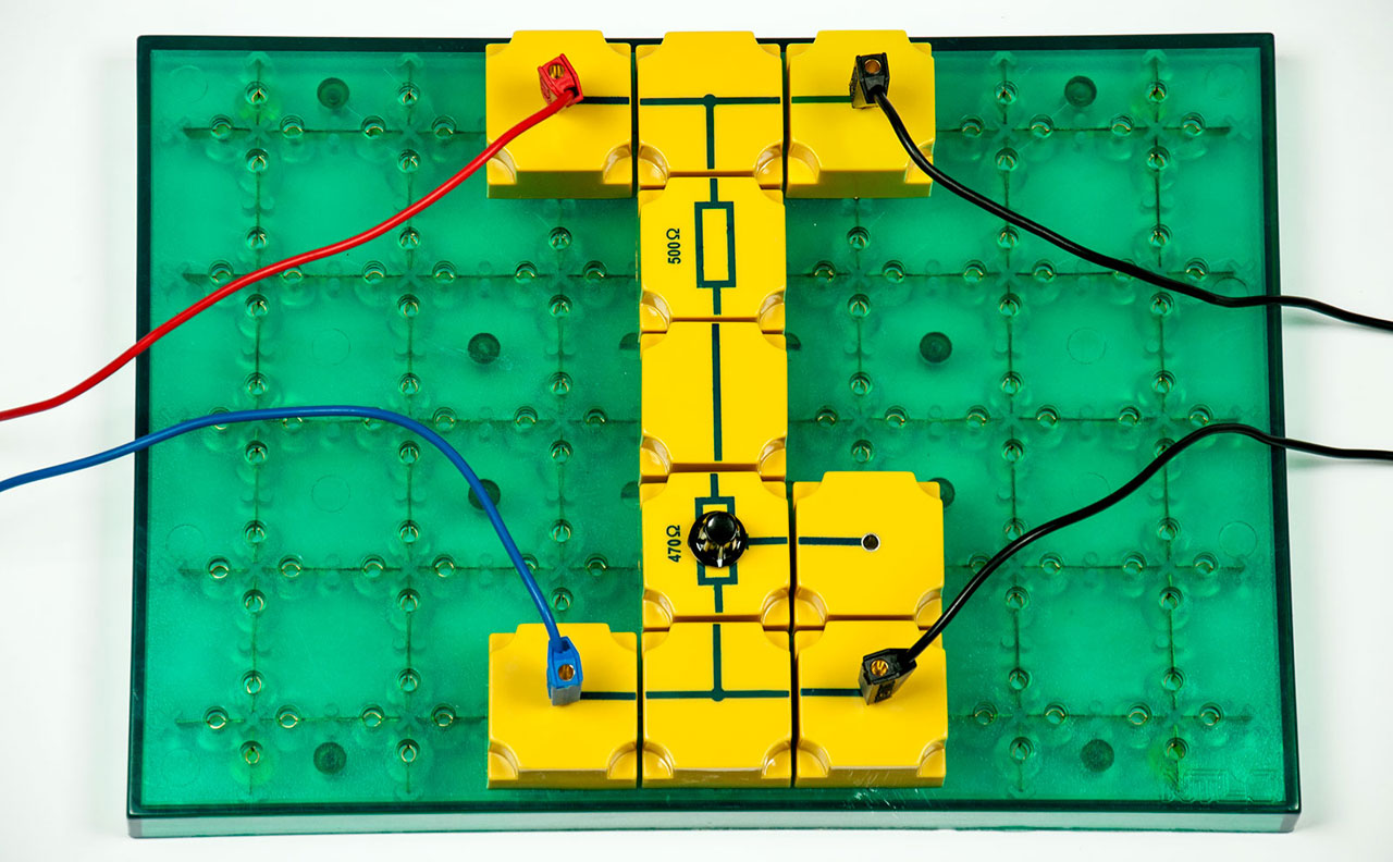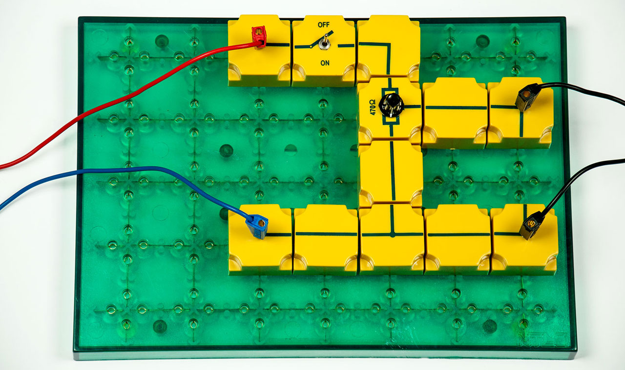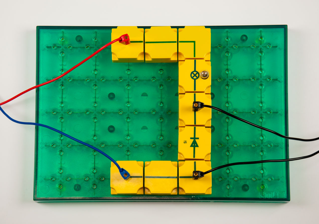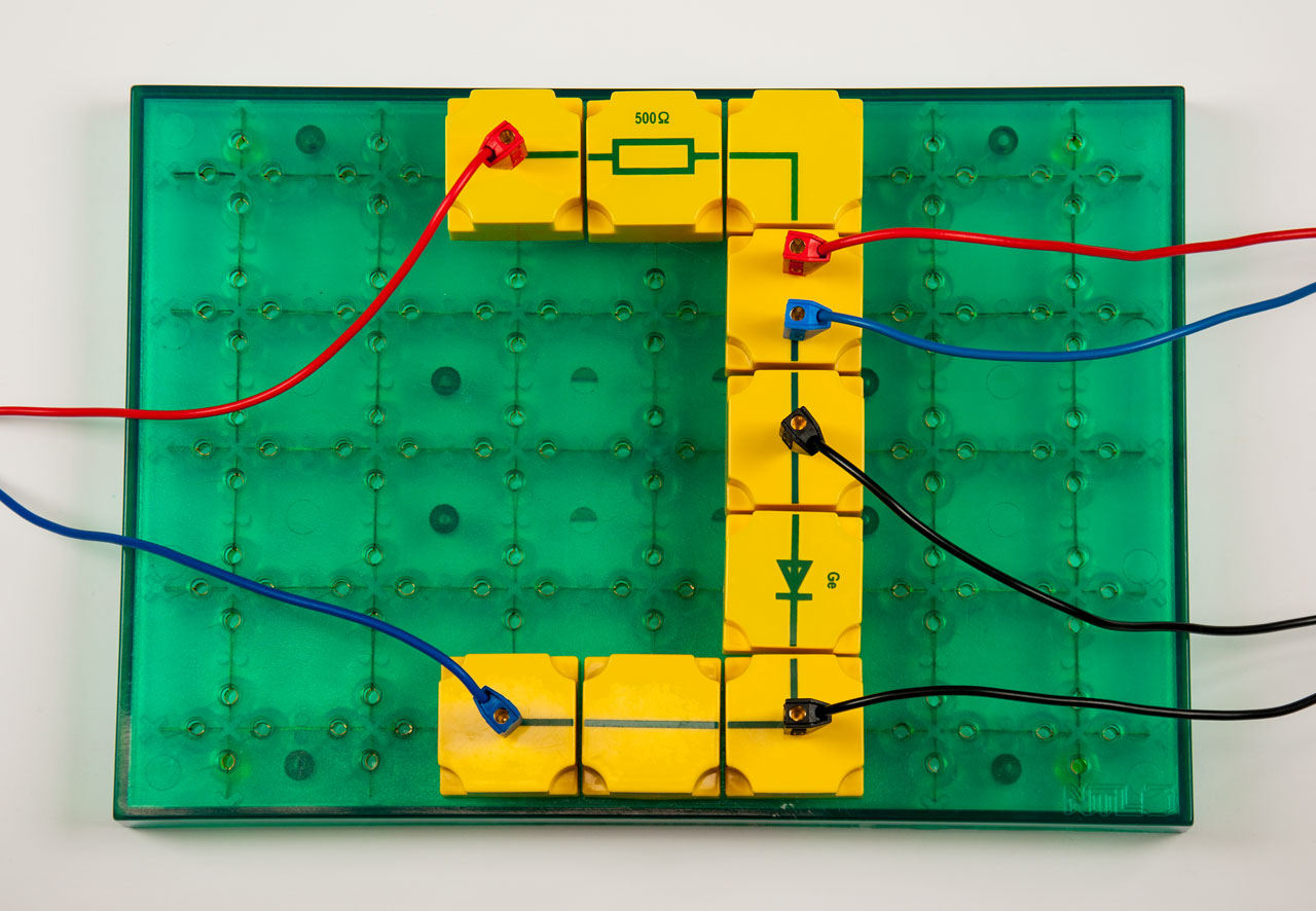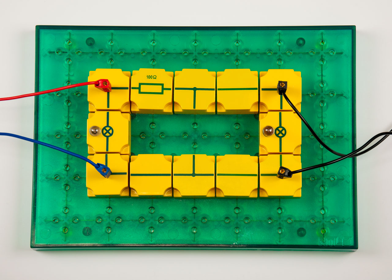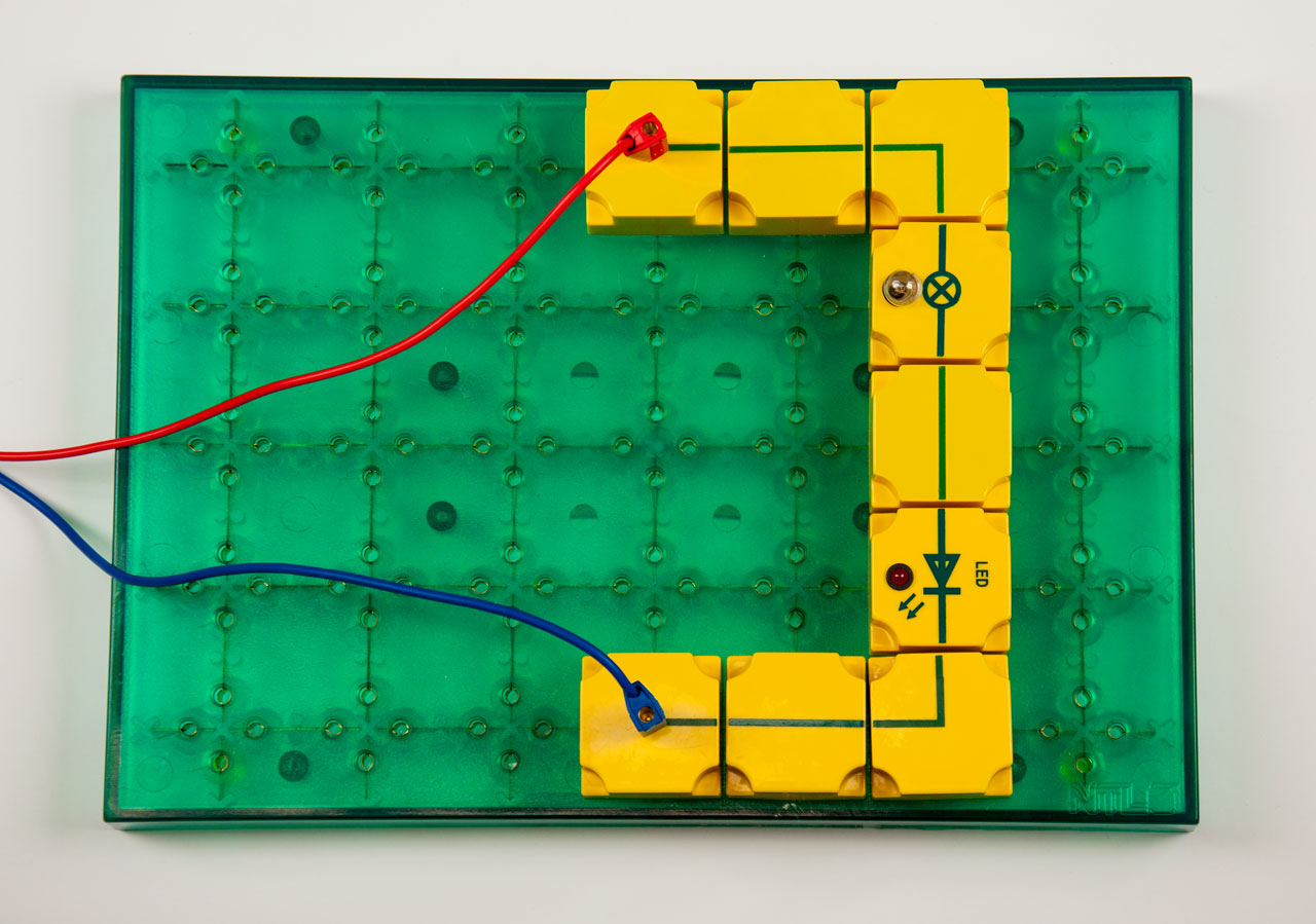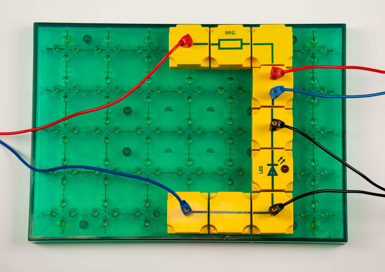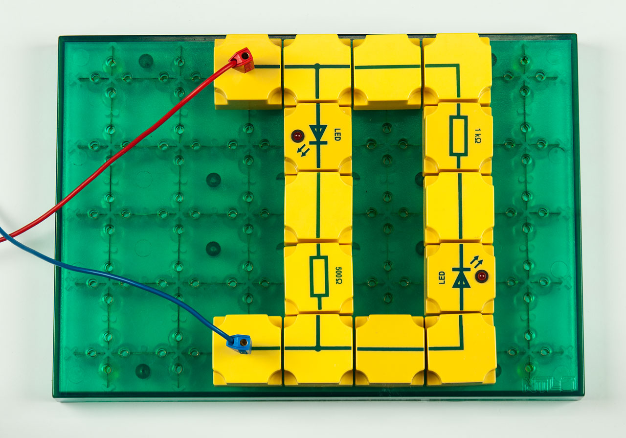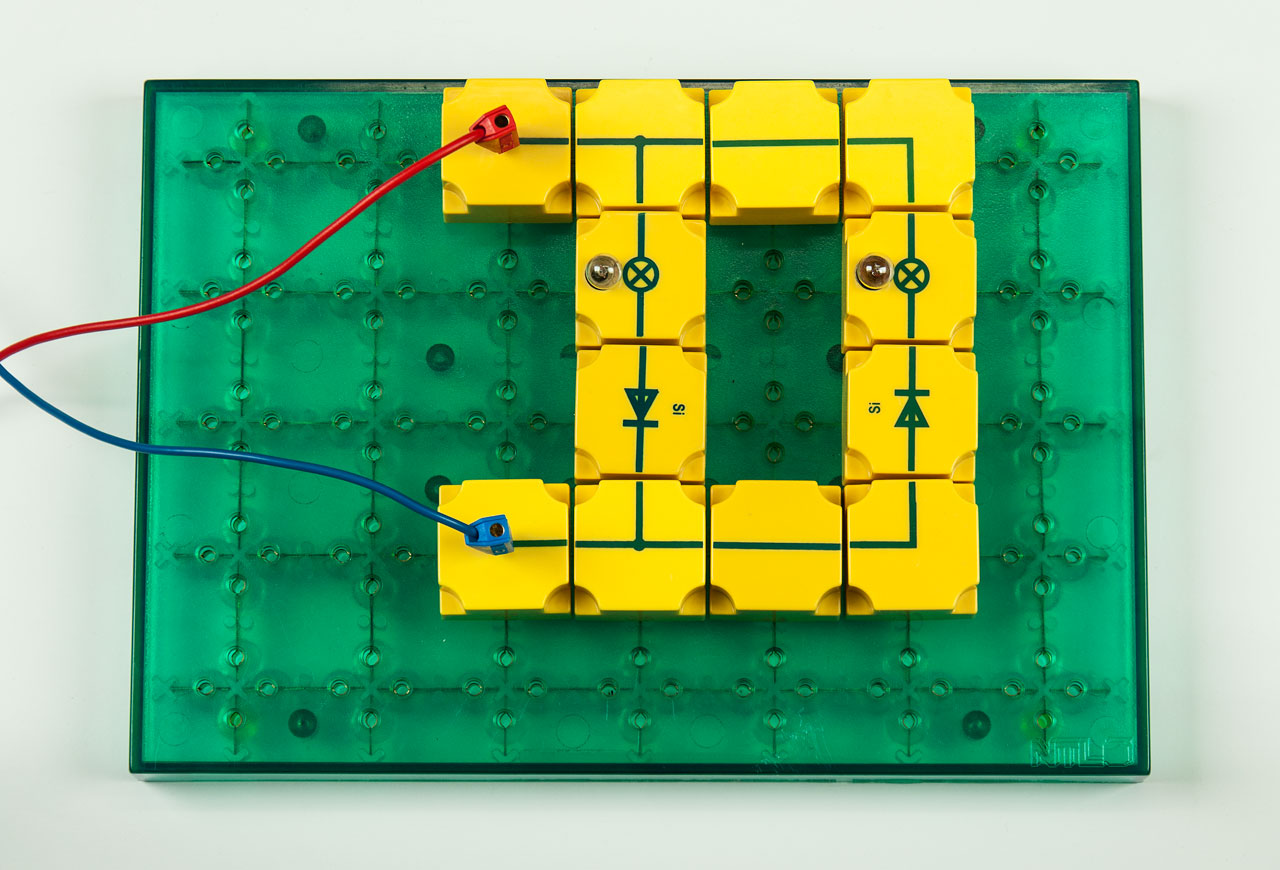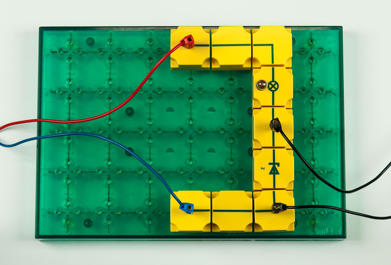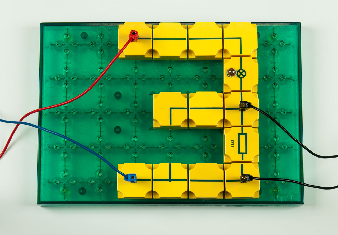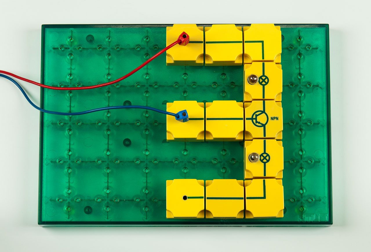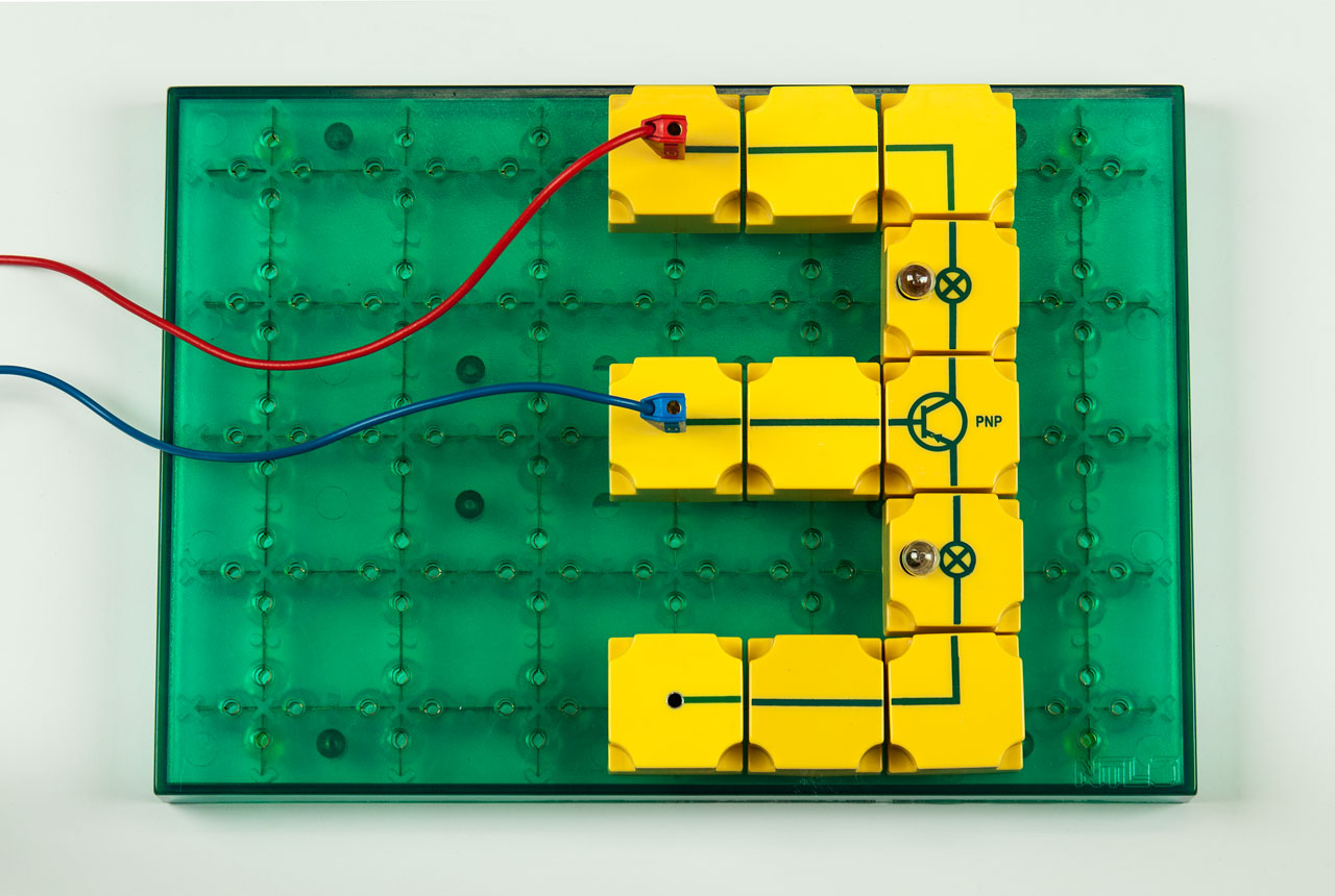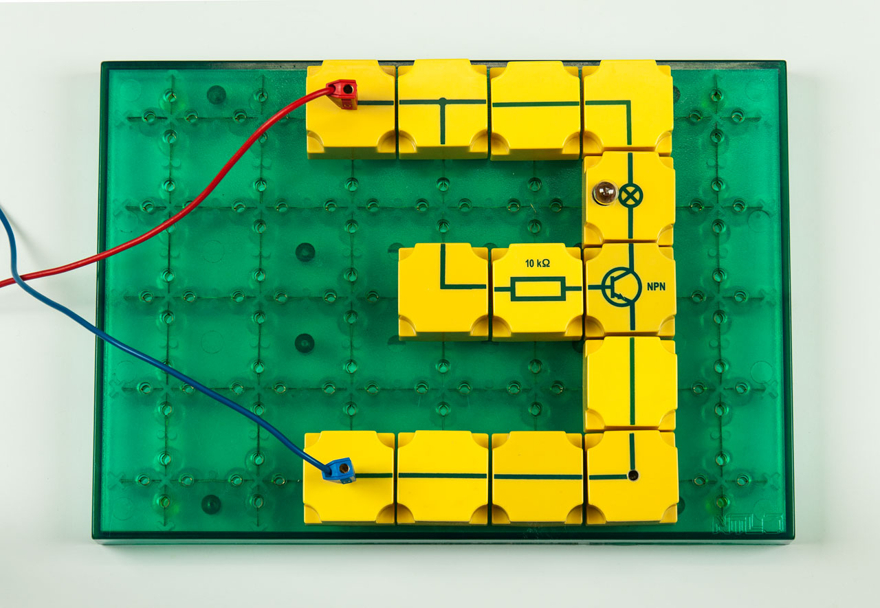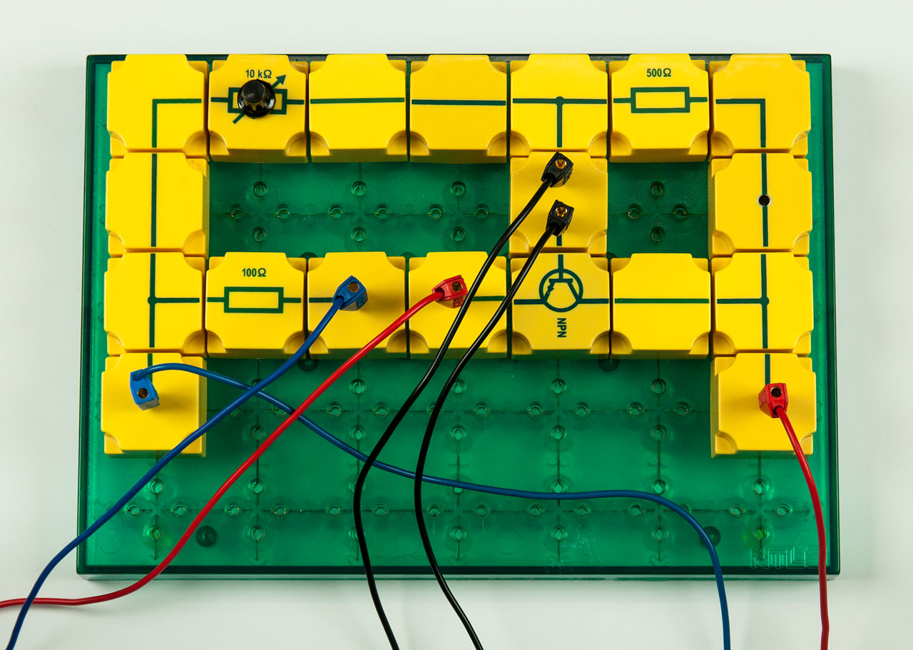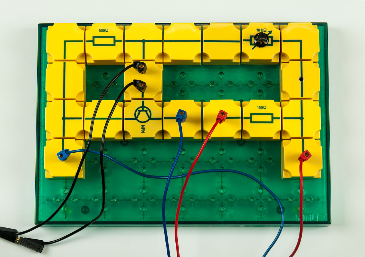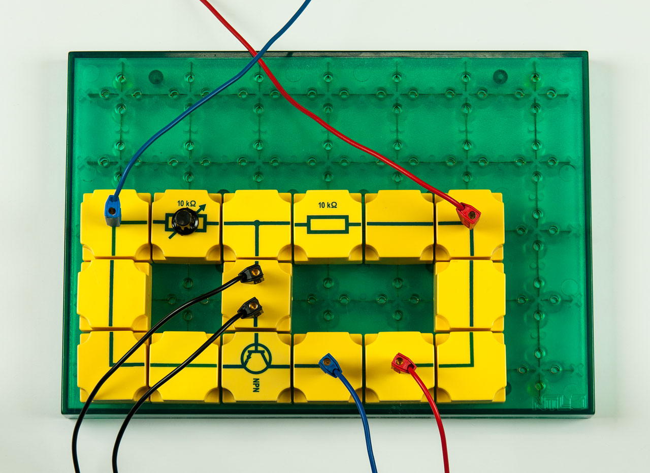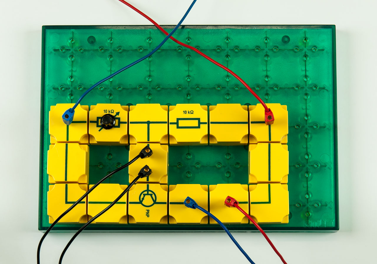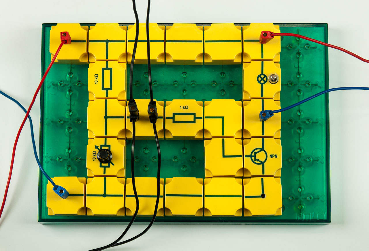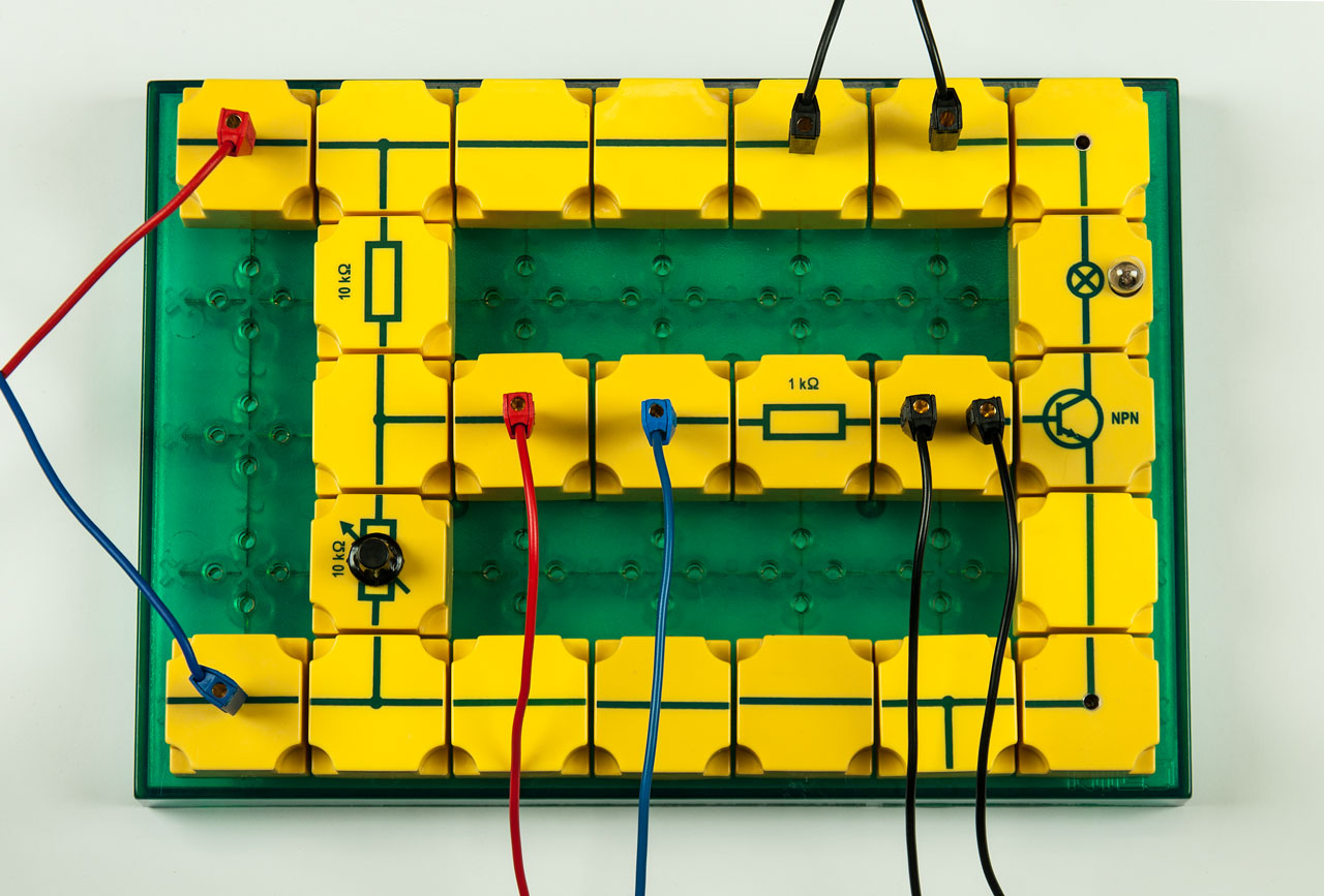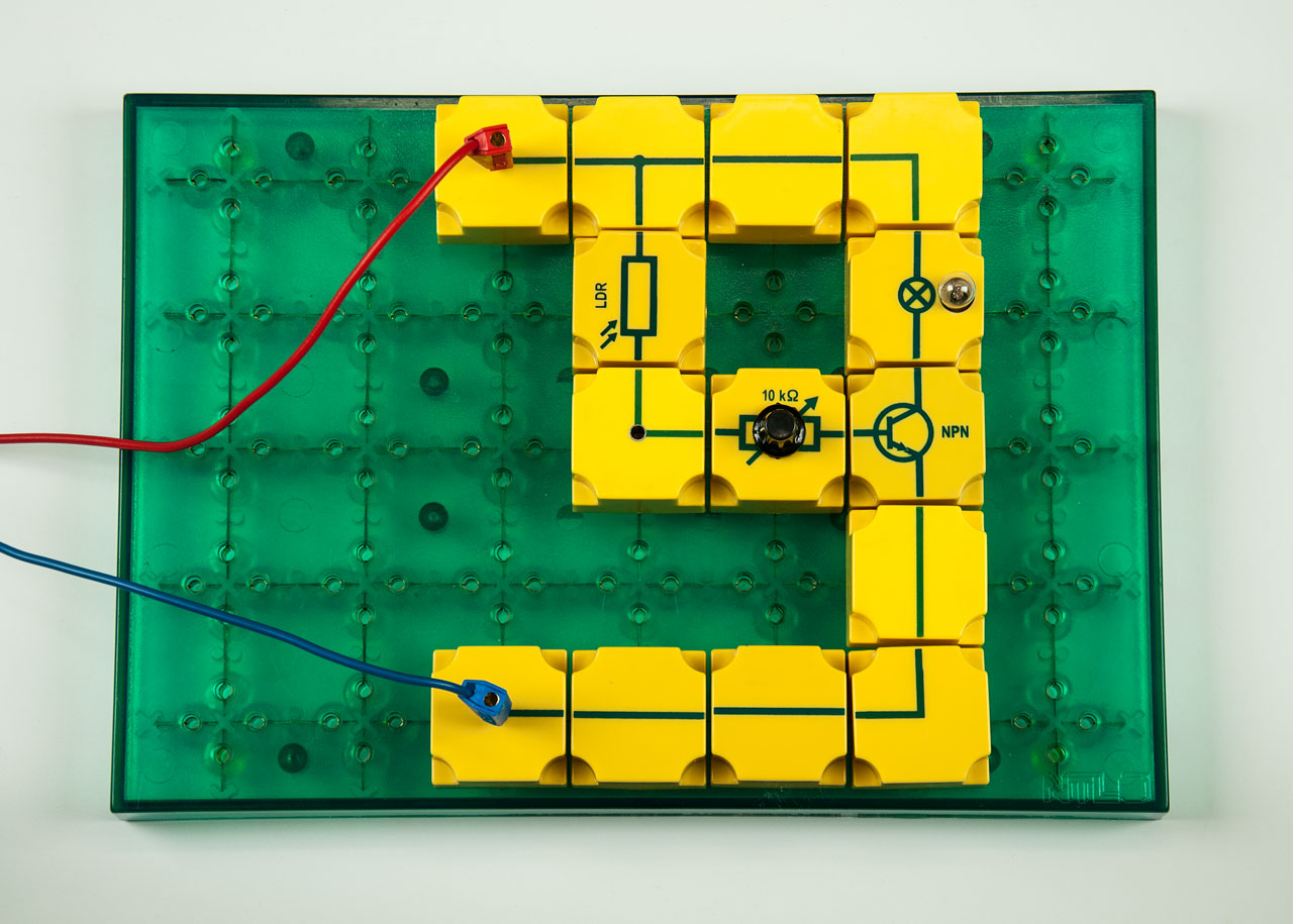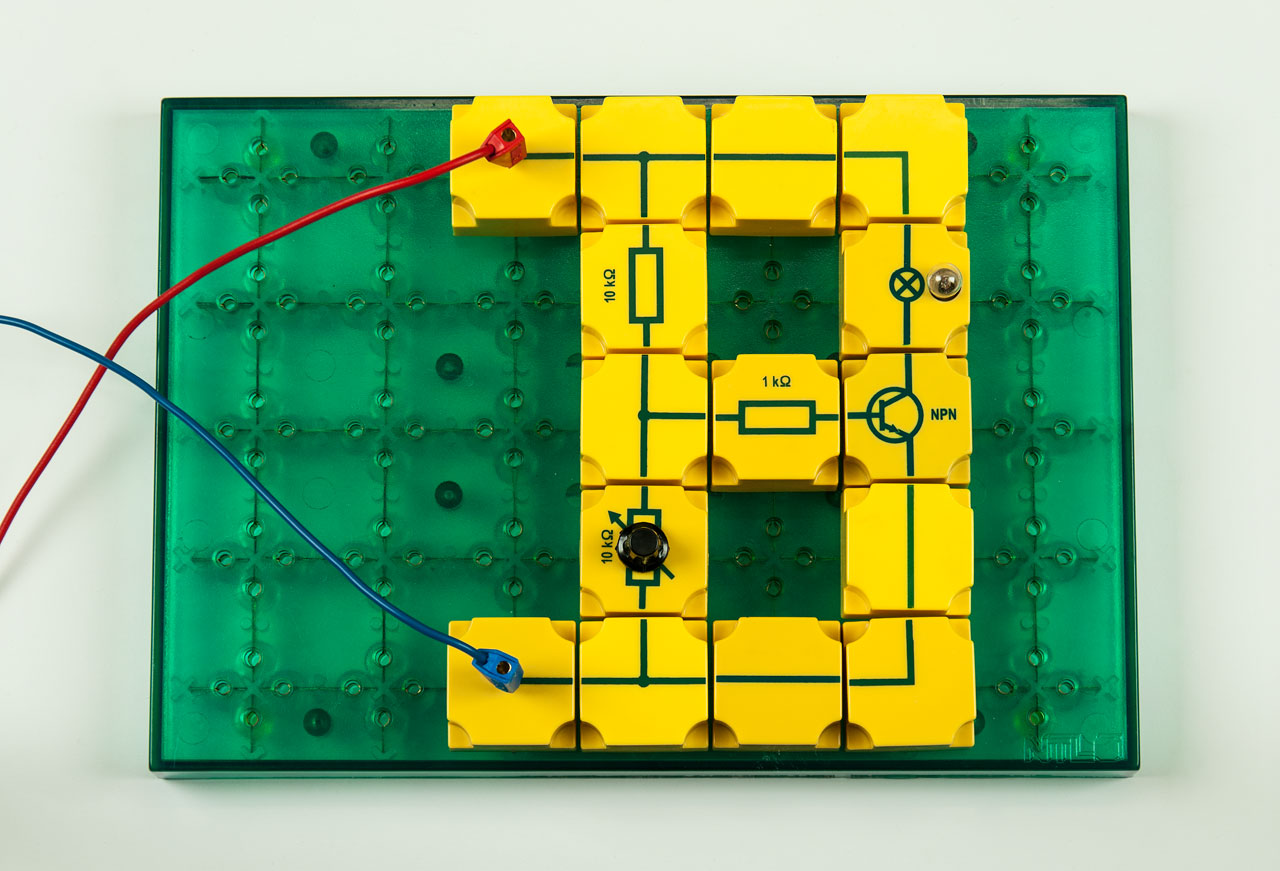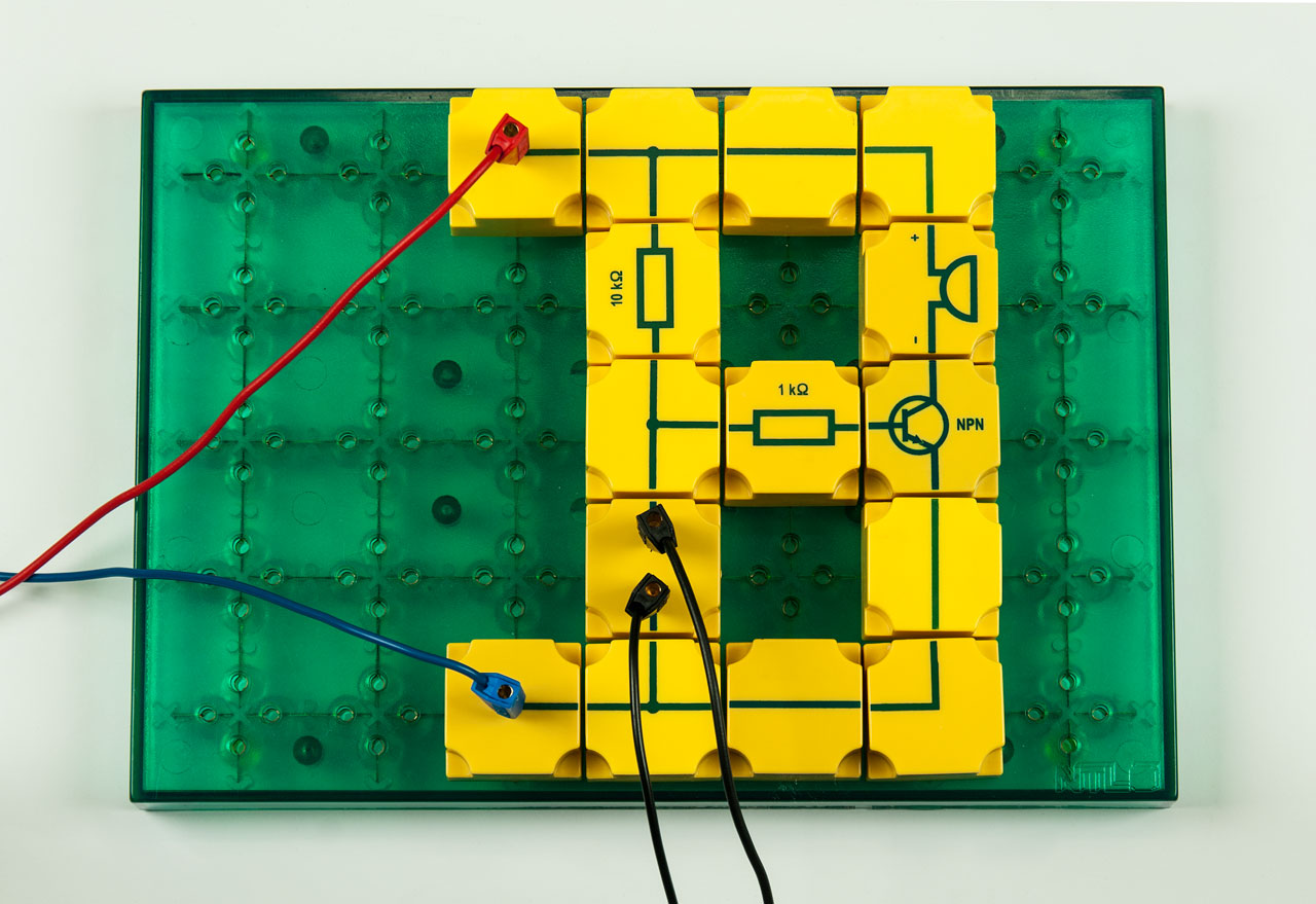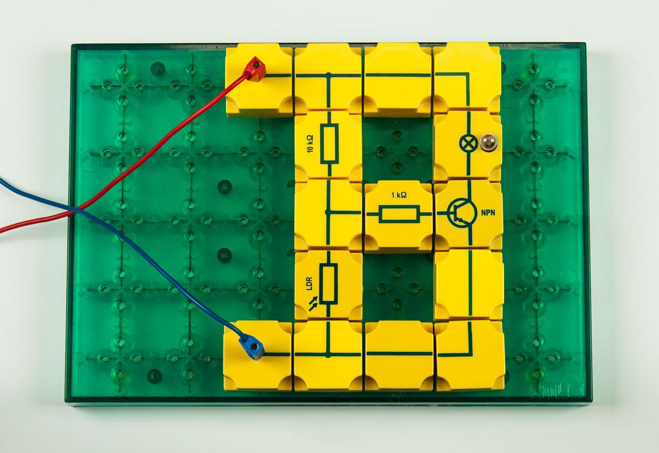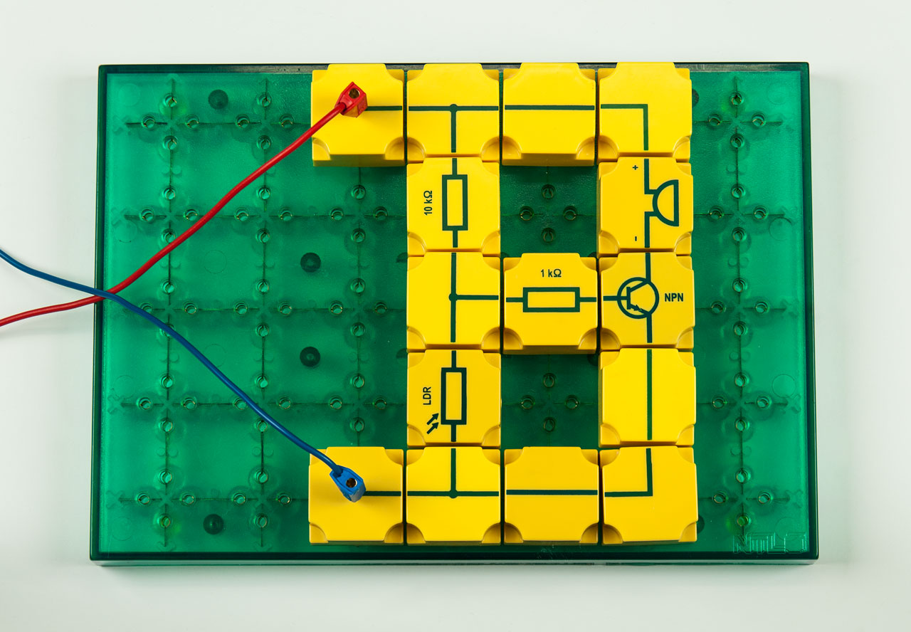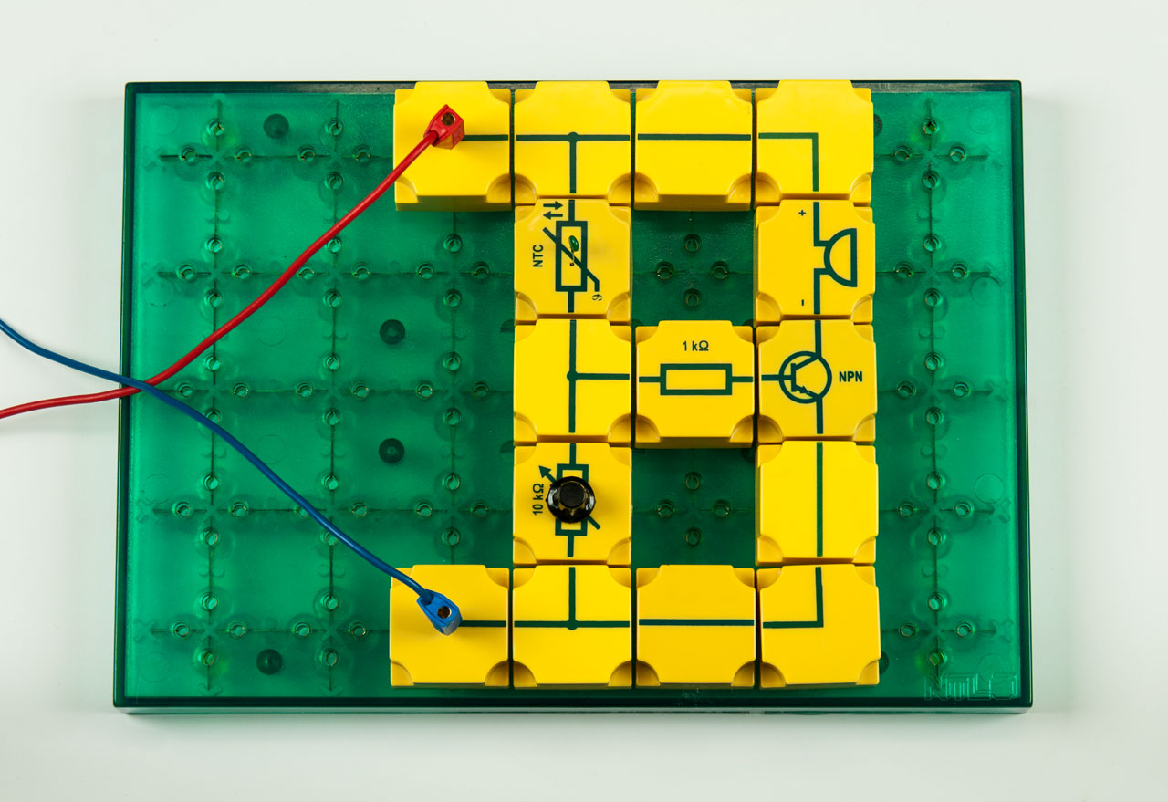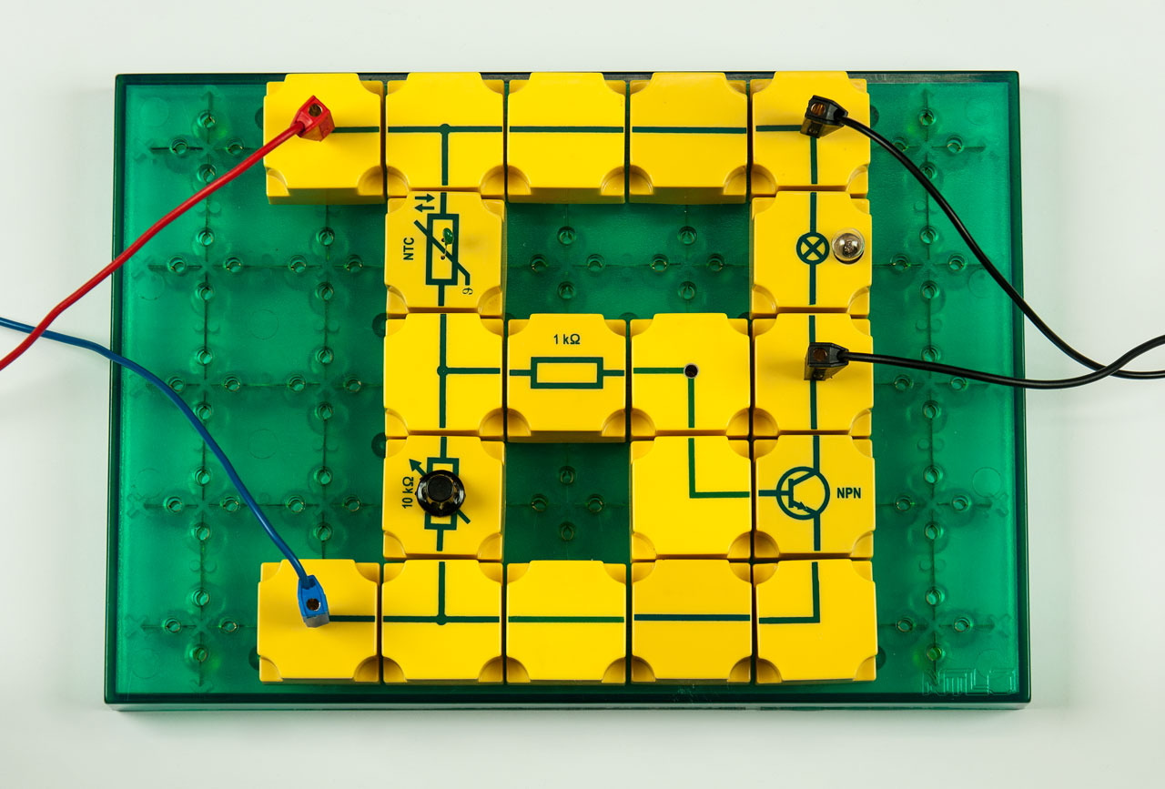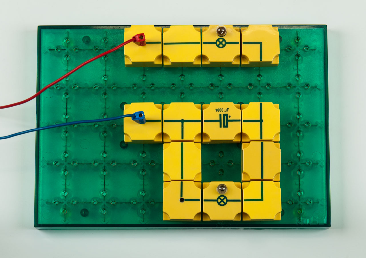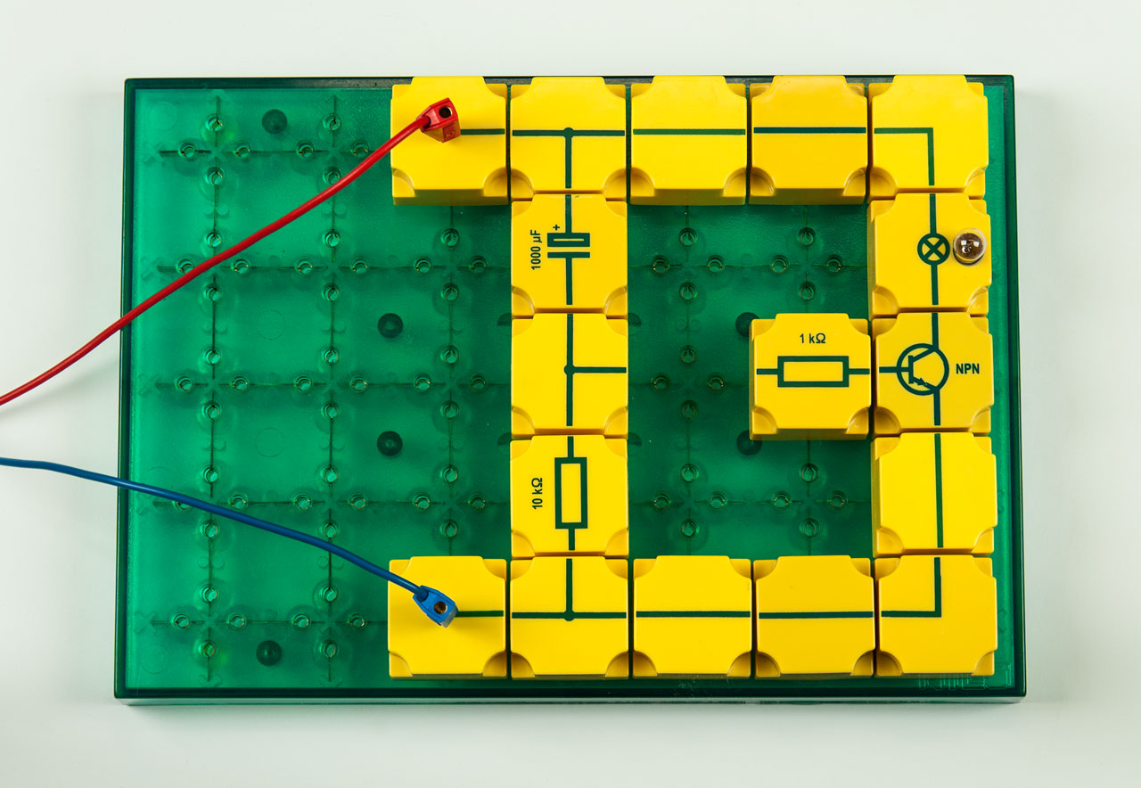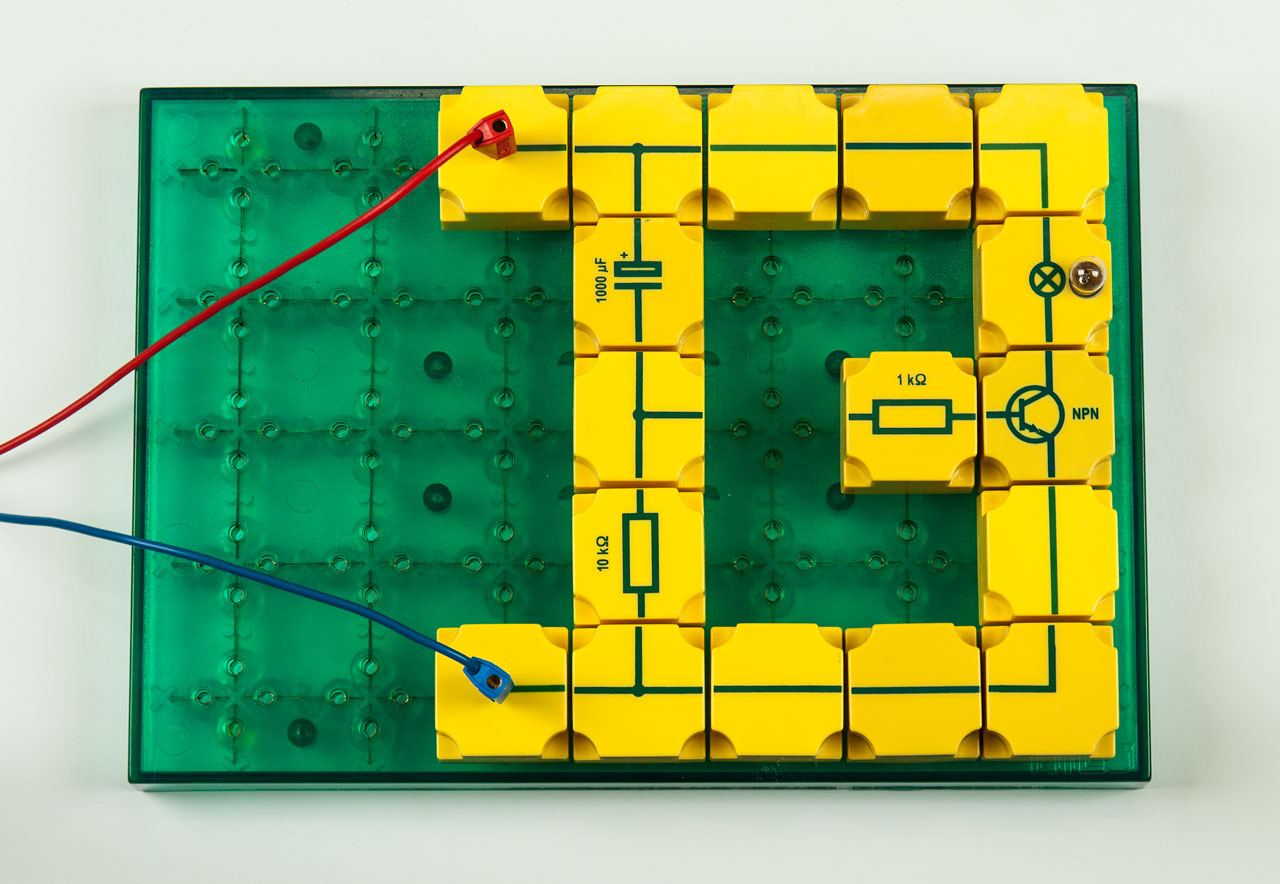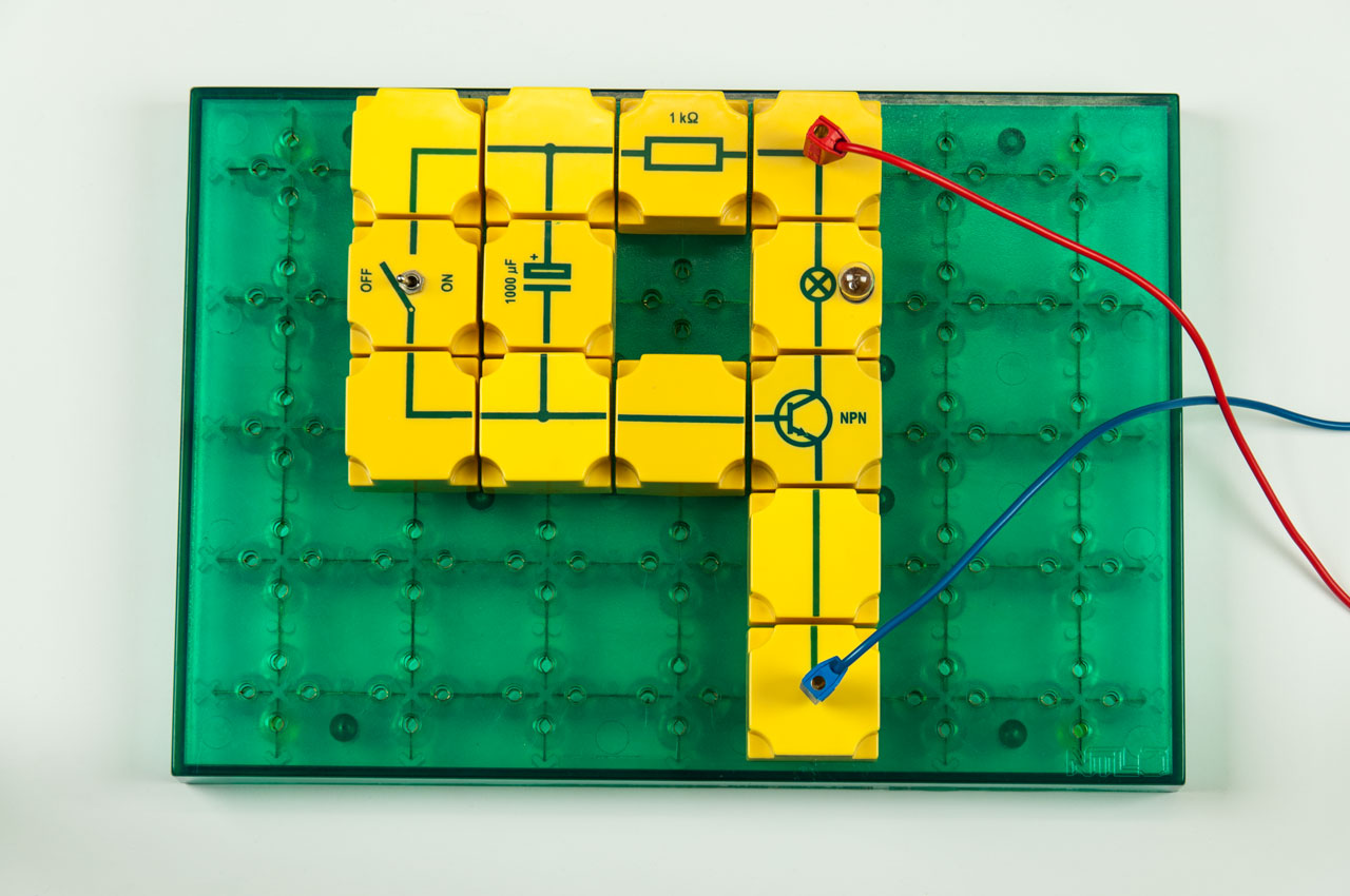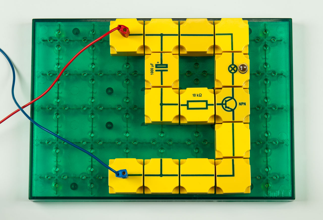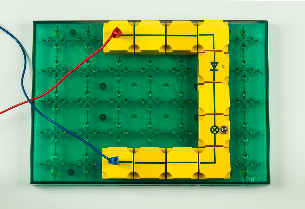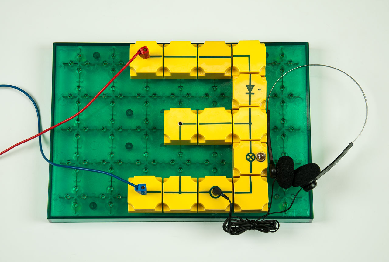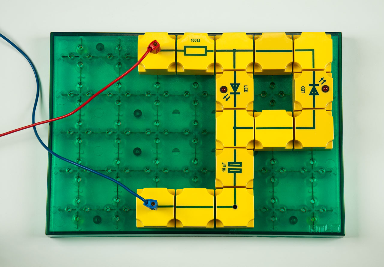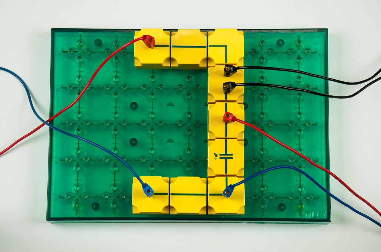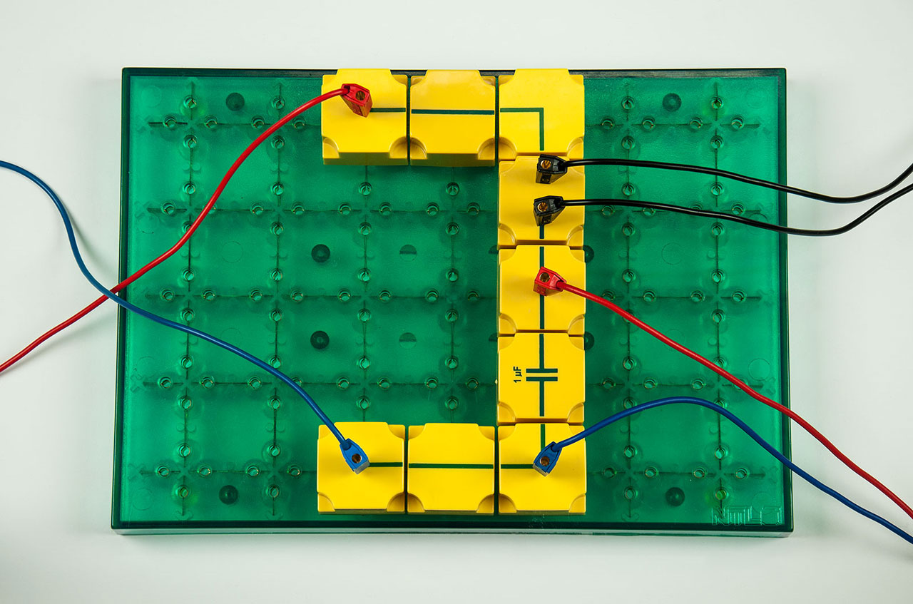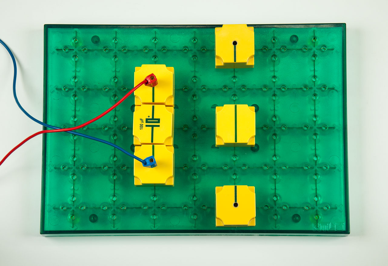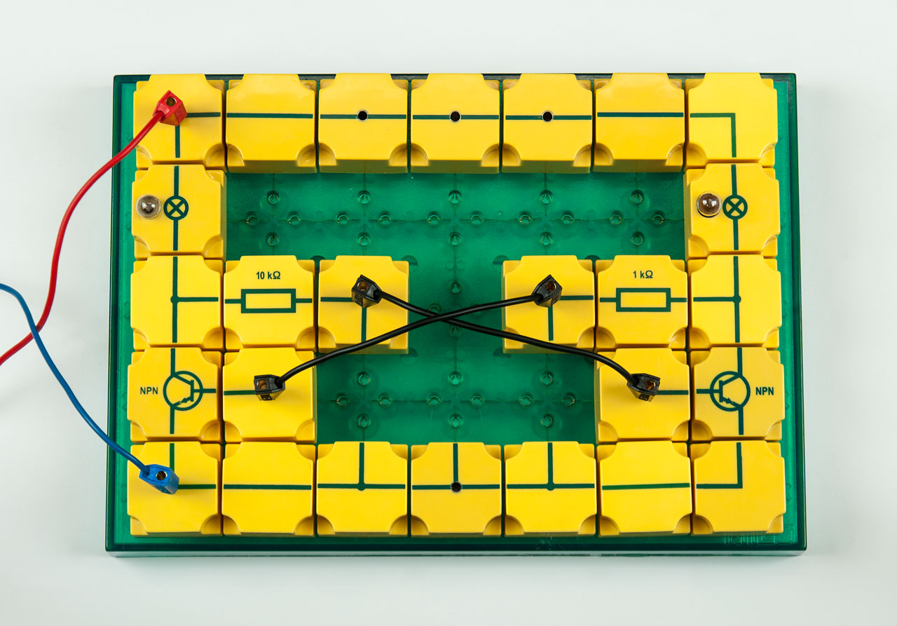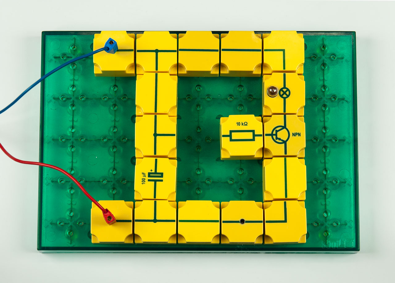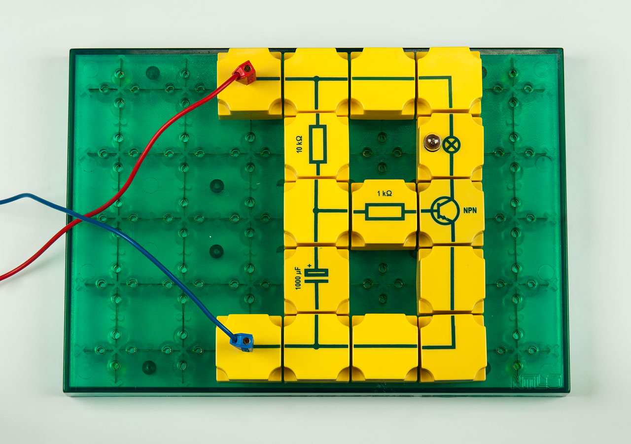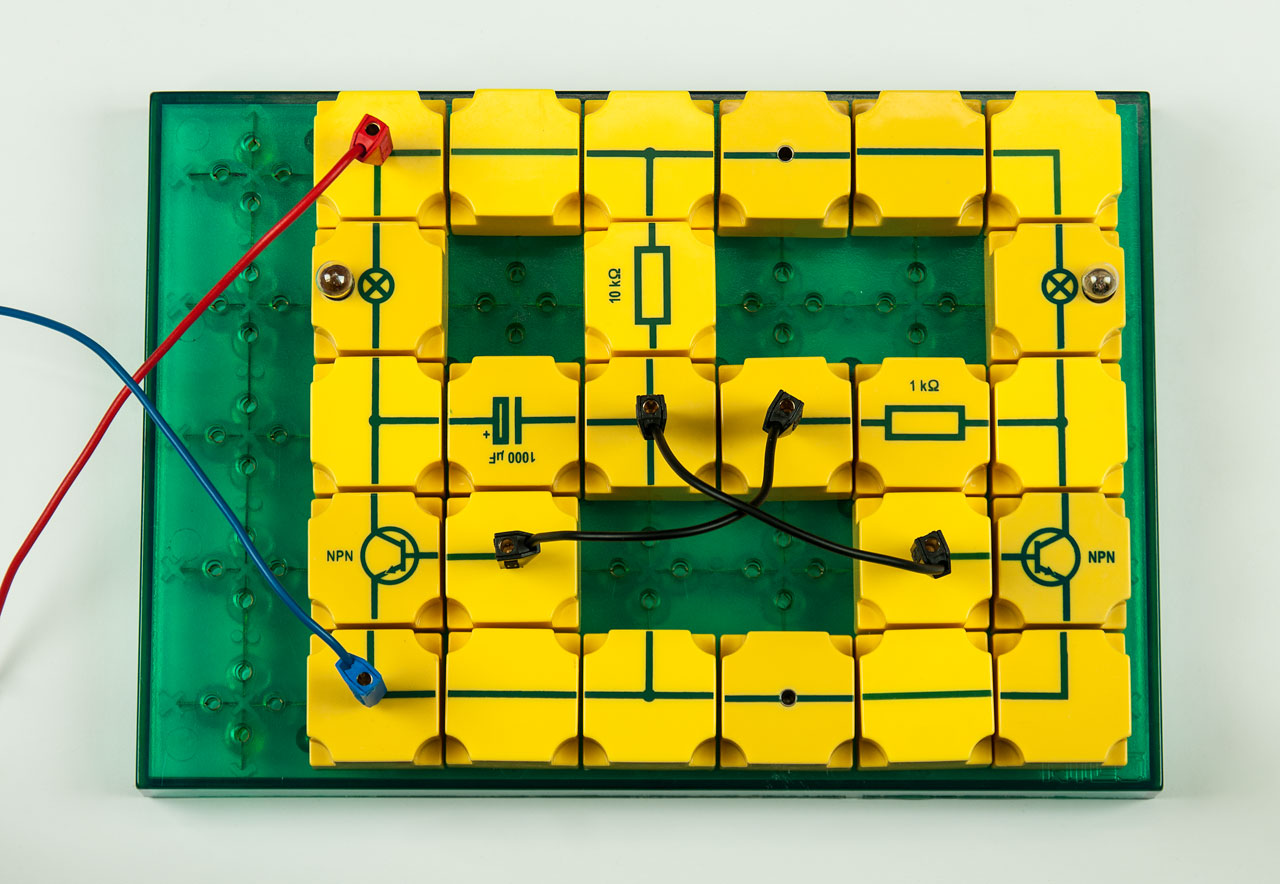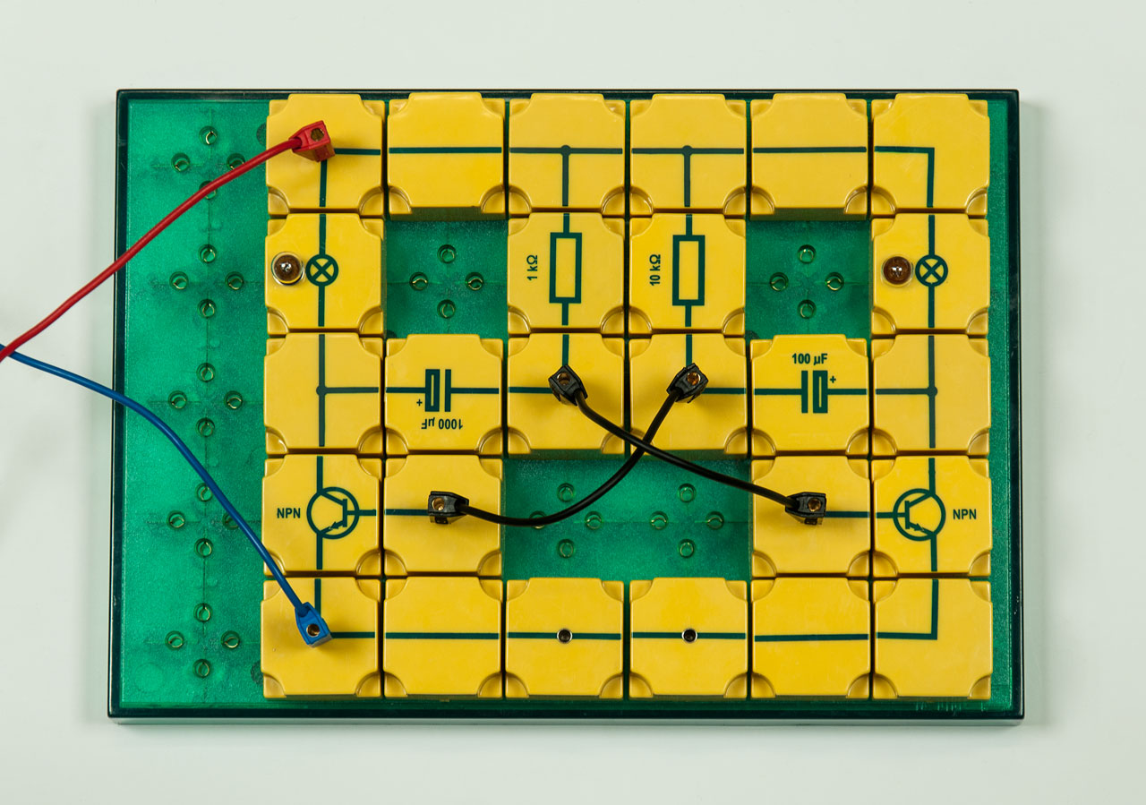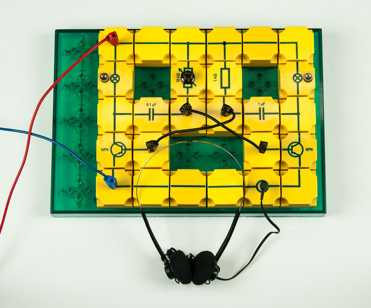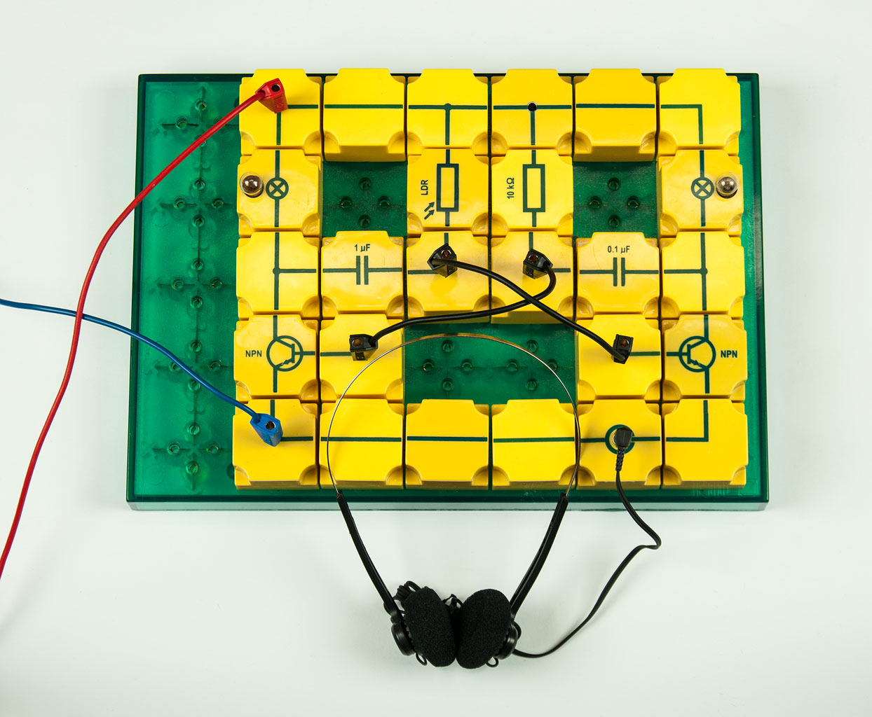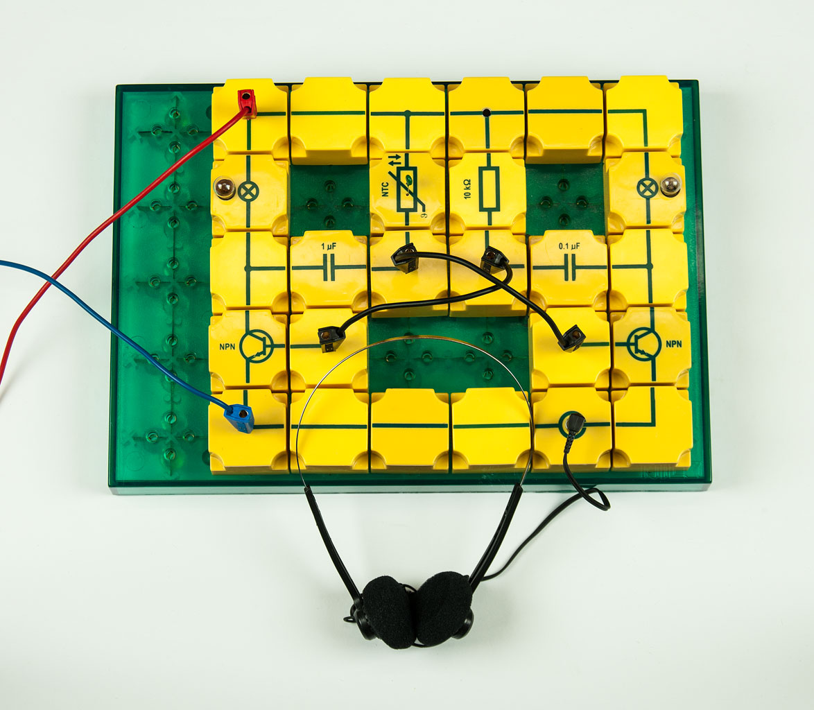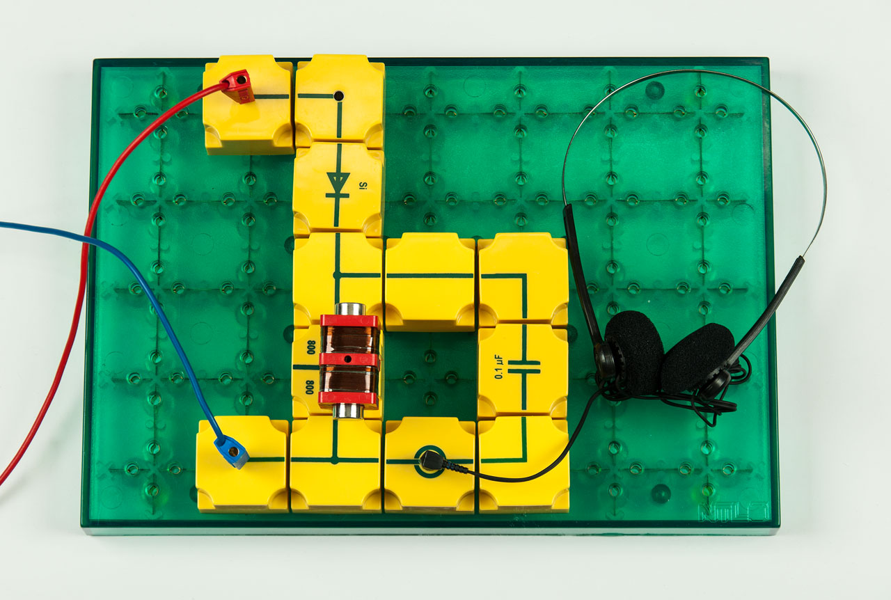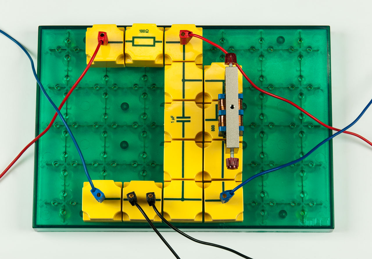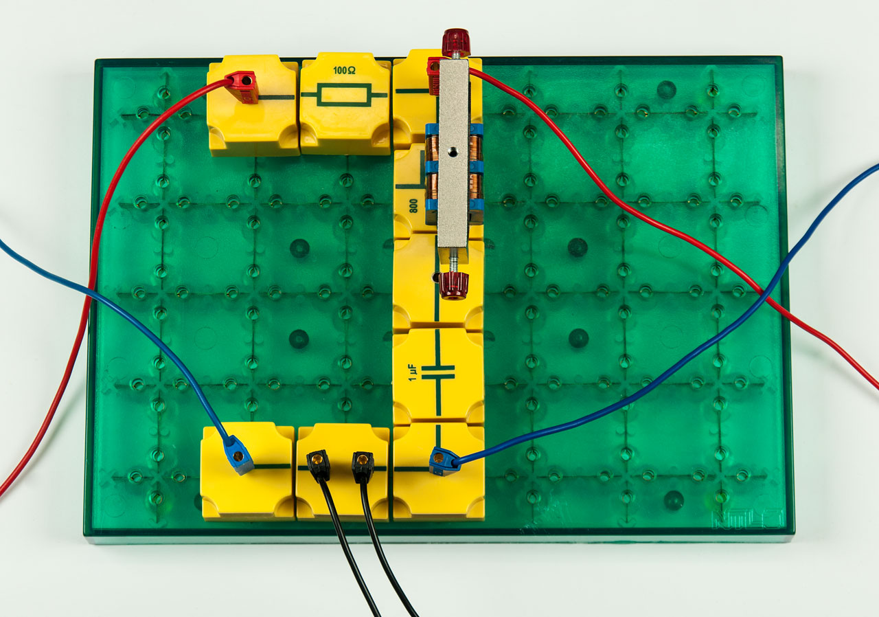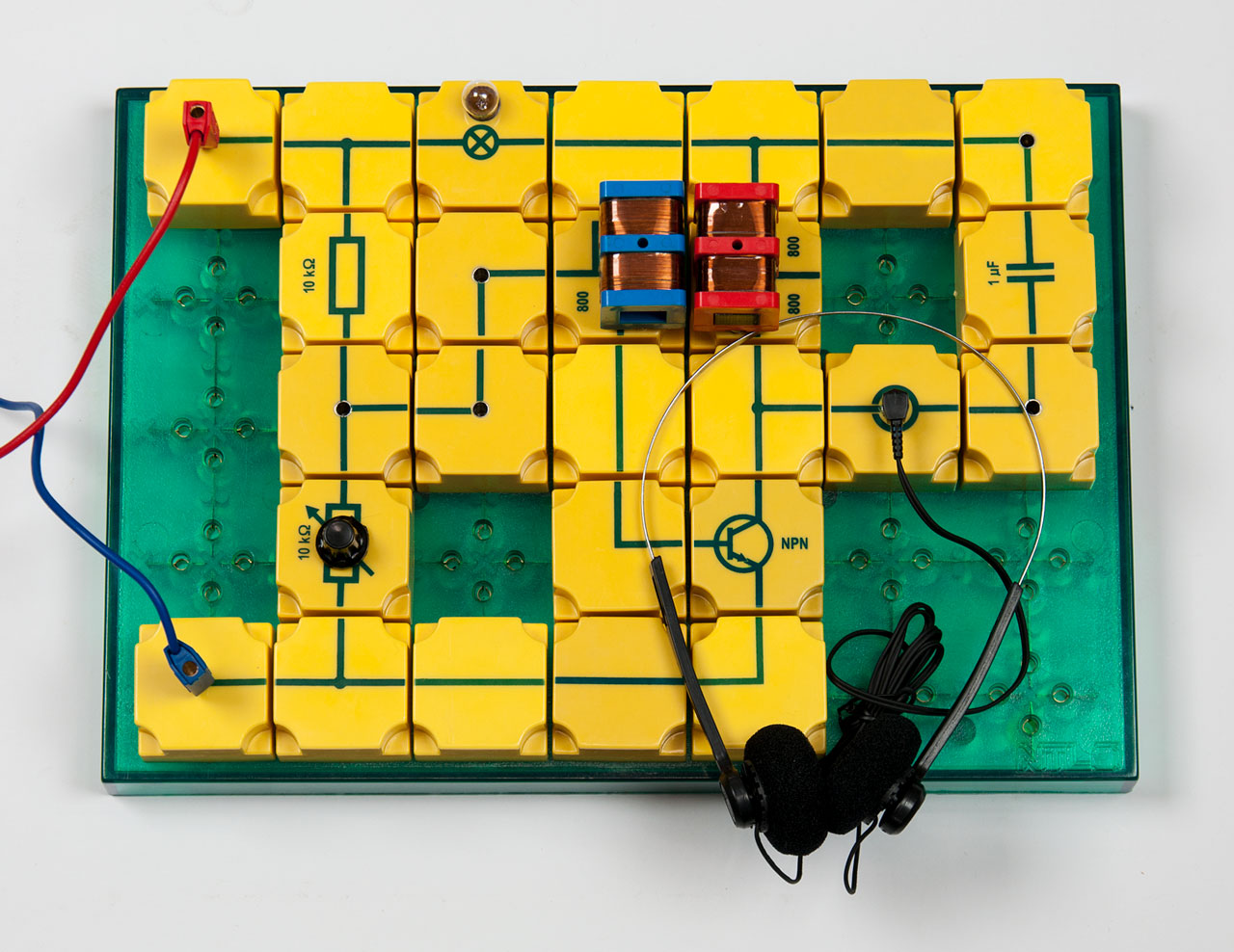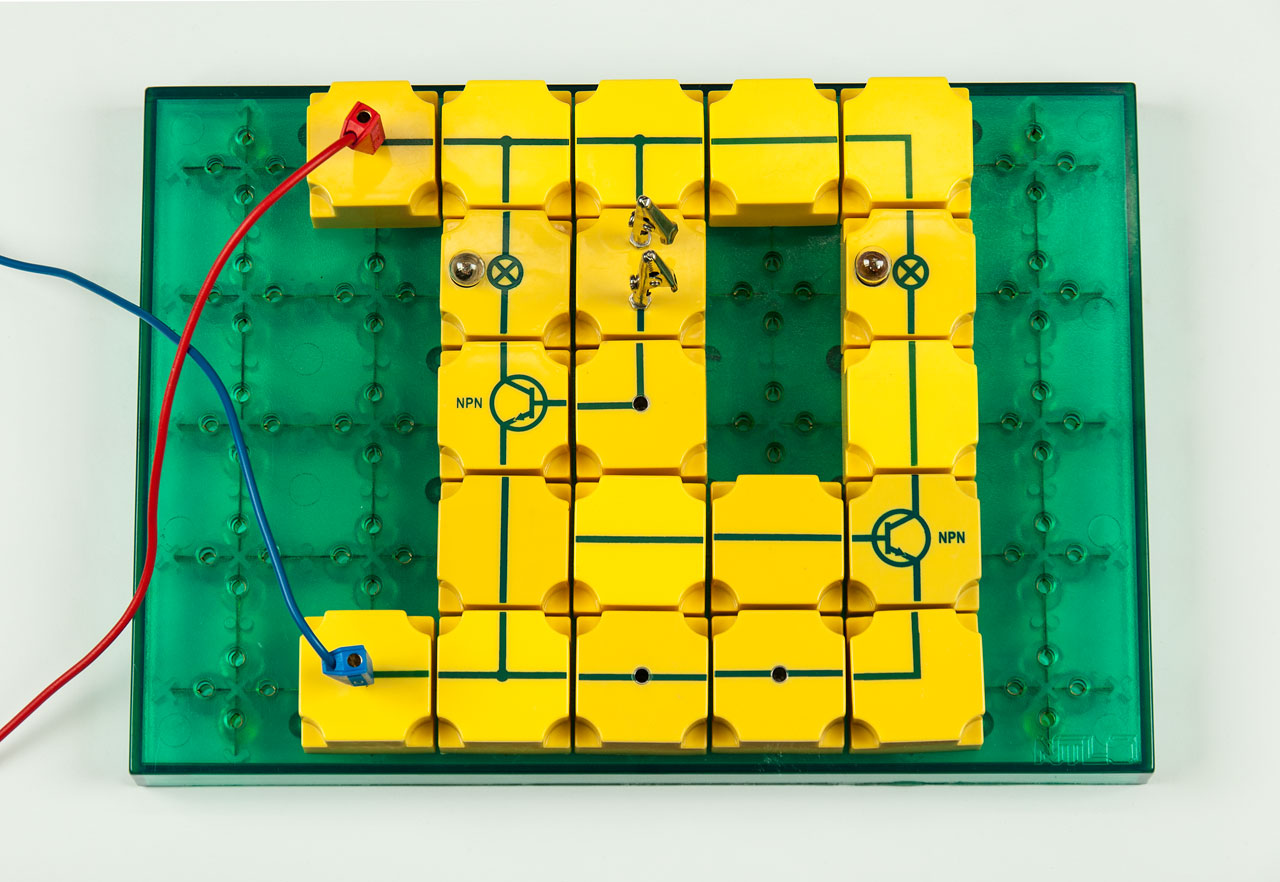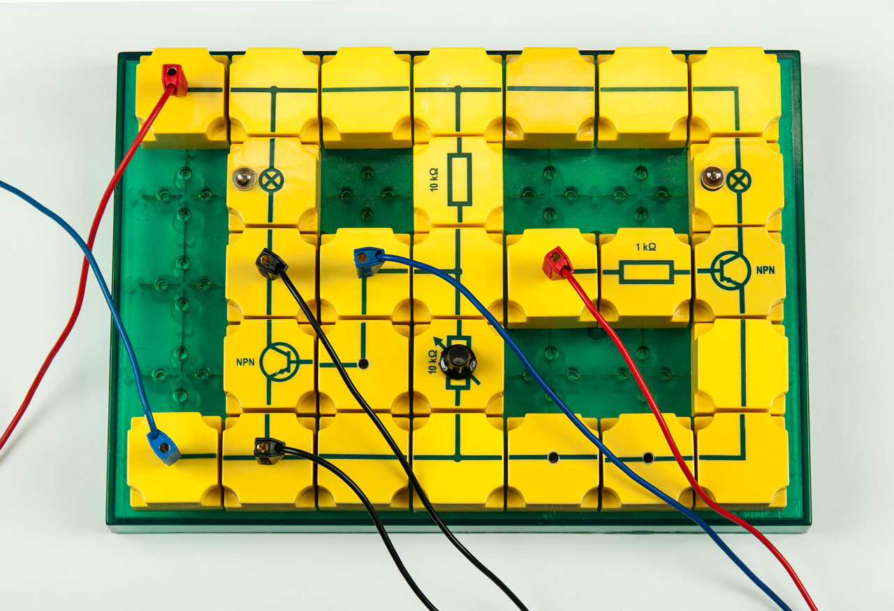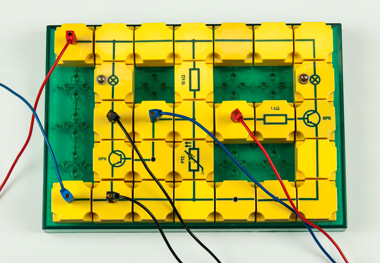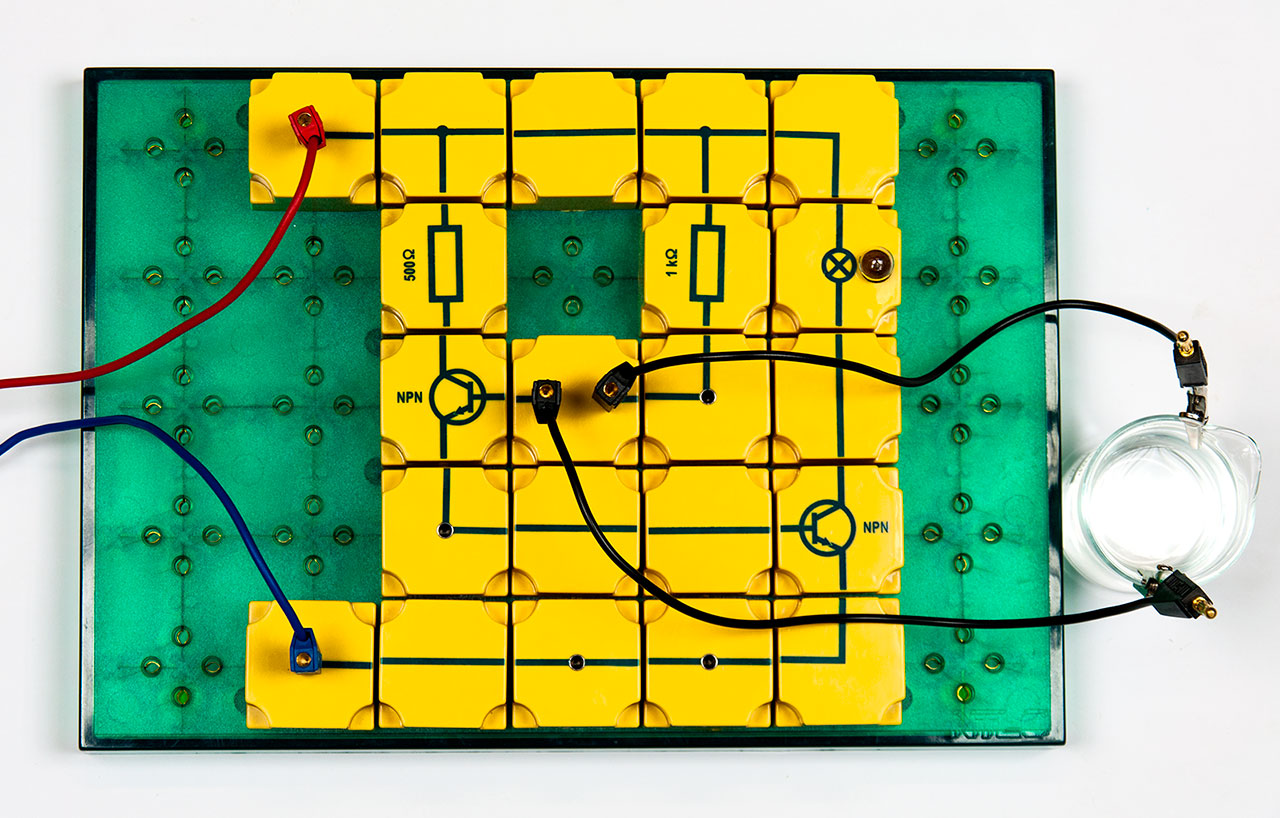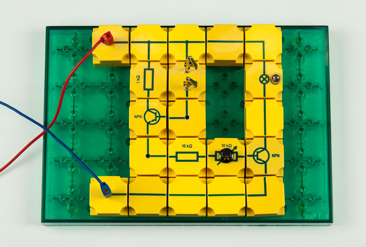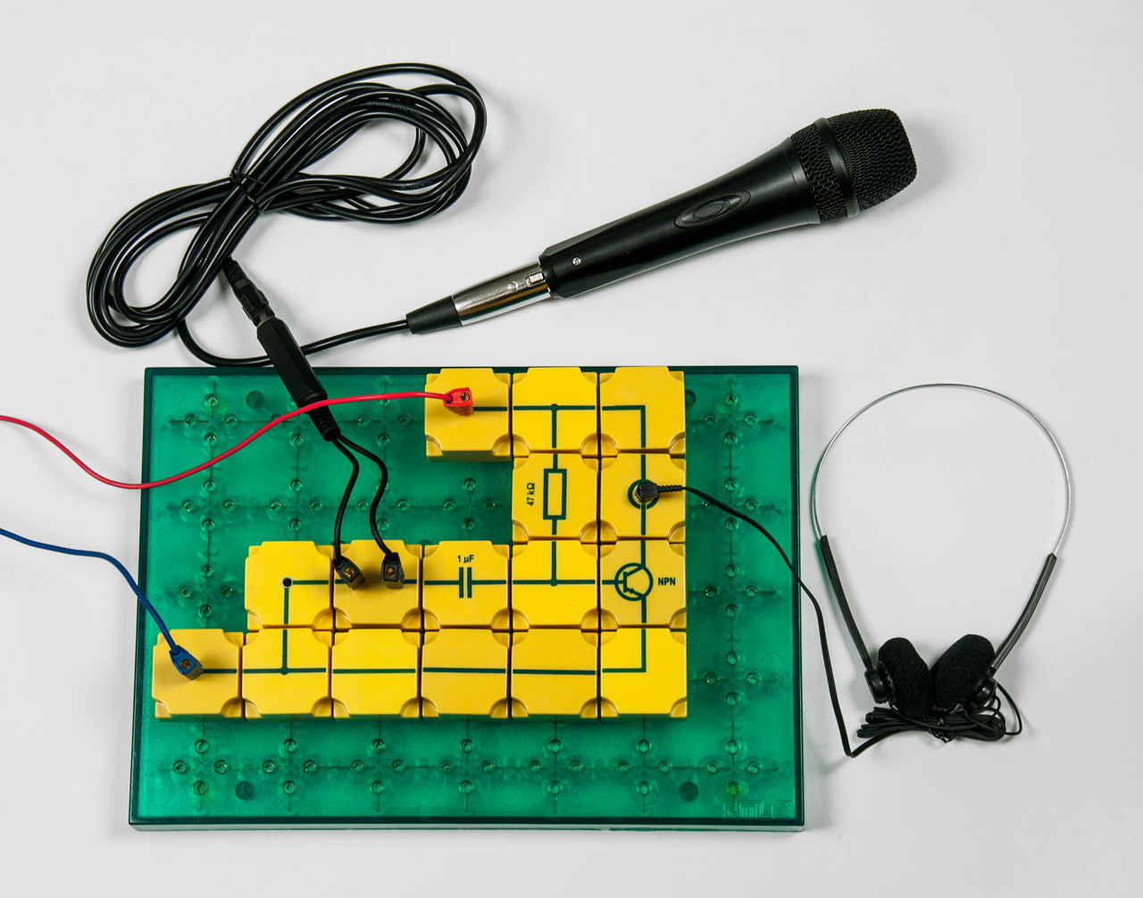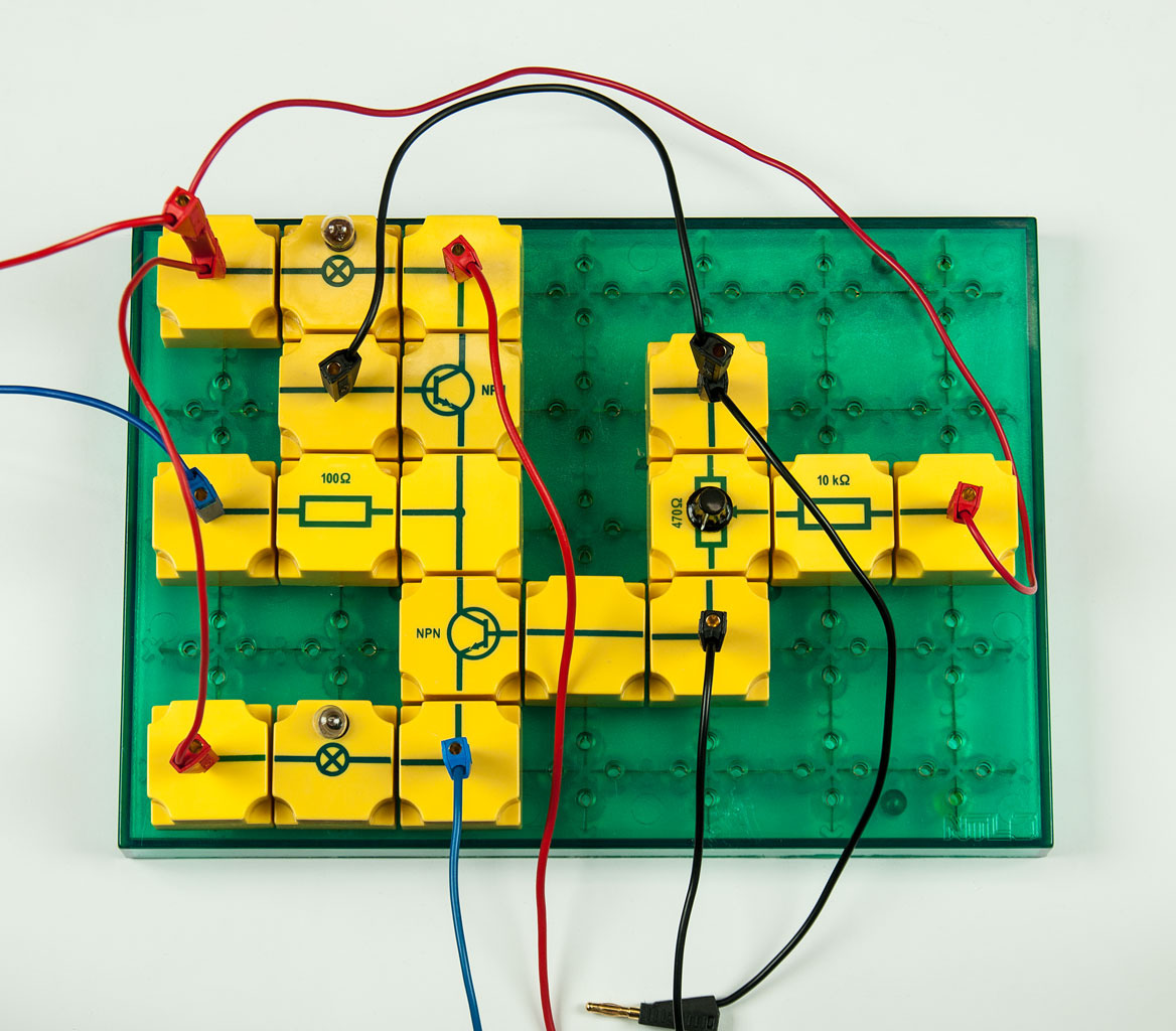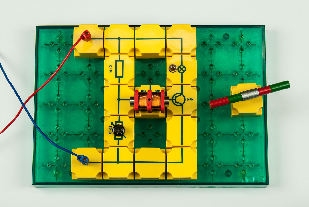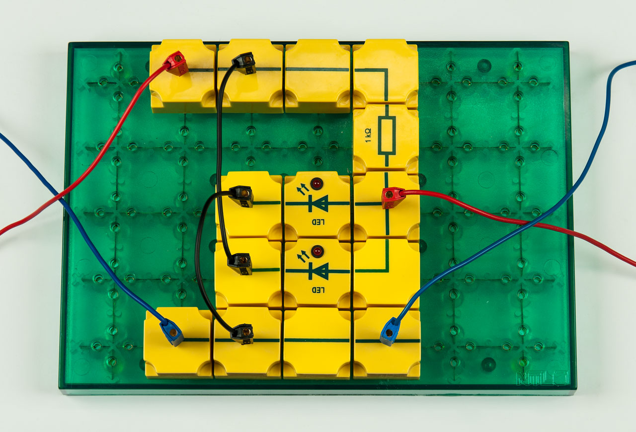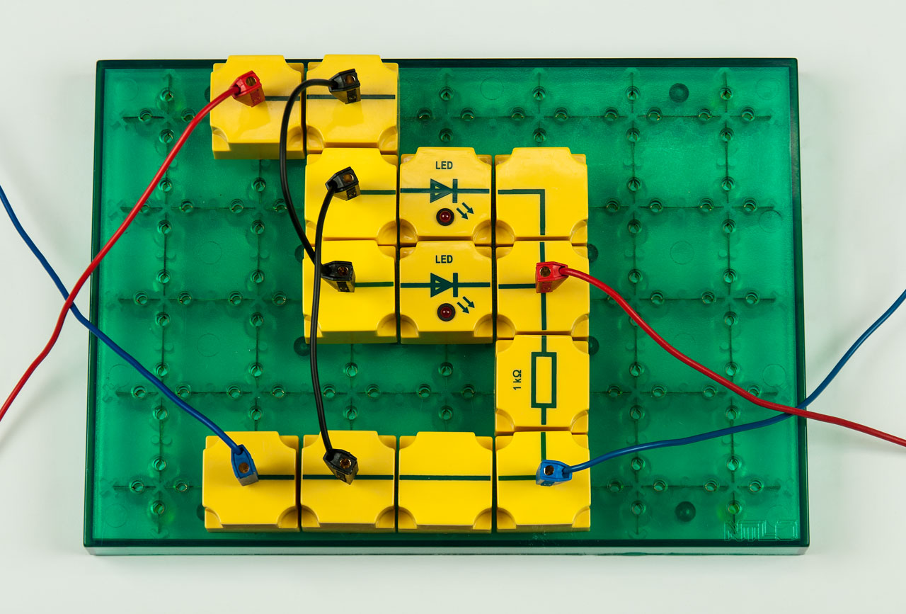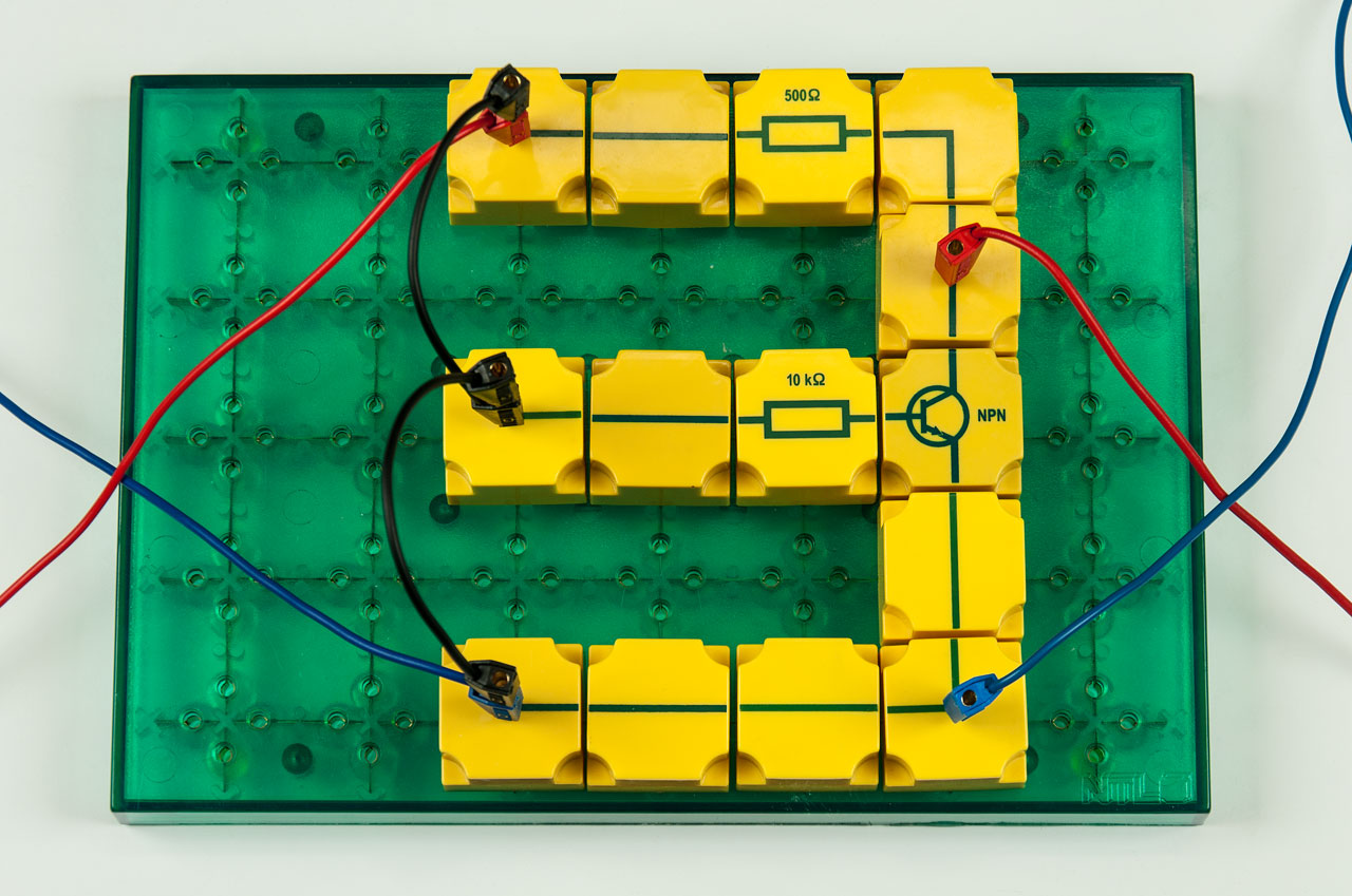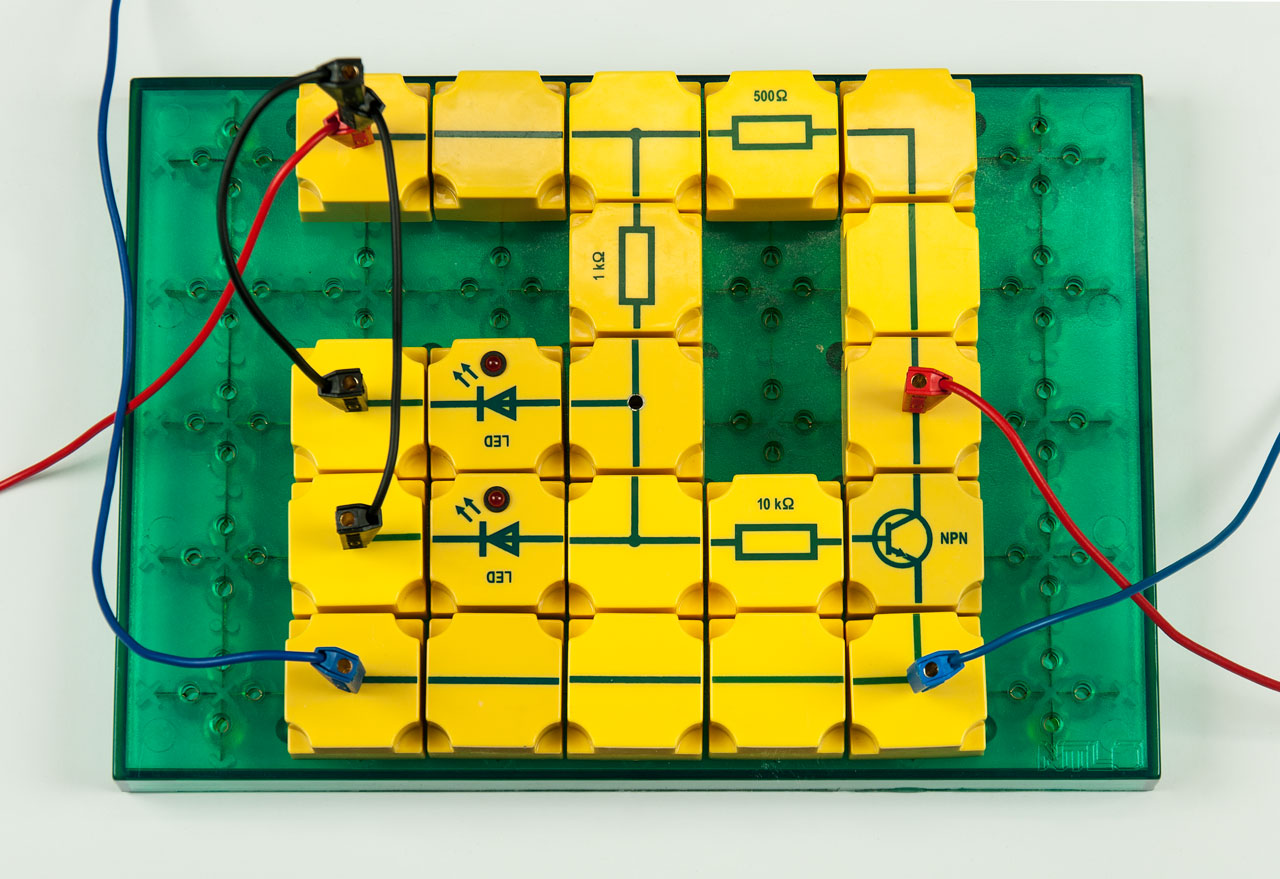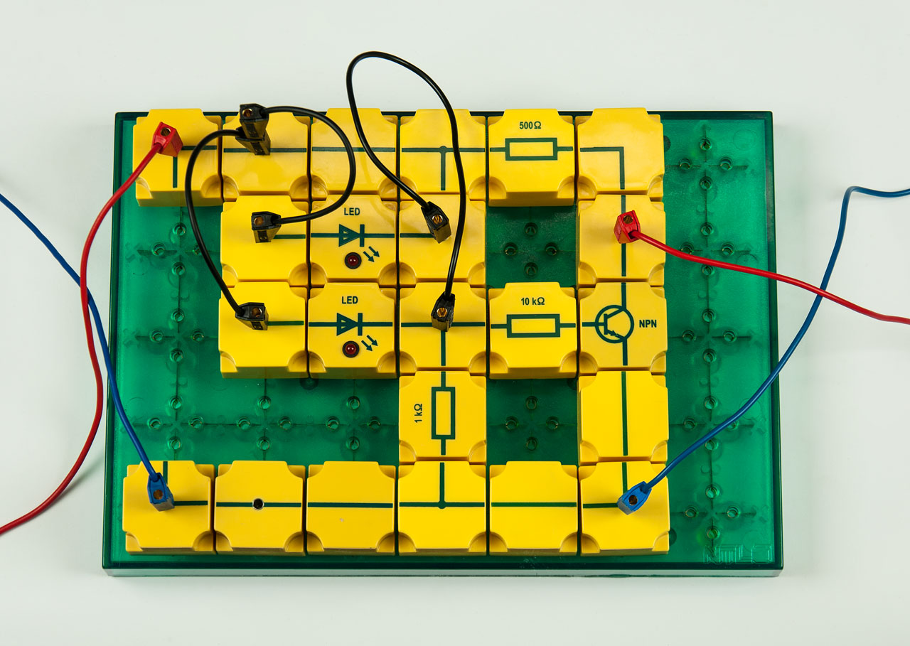
SEK Electronics complete

P9901-4M
Price on request
Recycle Seal

This student experiment box requires accessories!

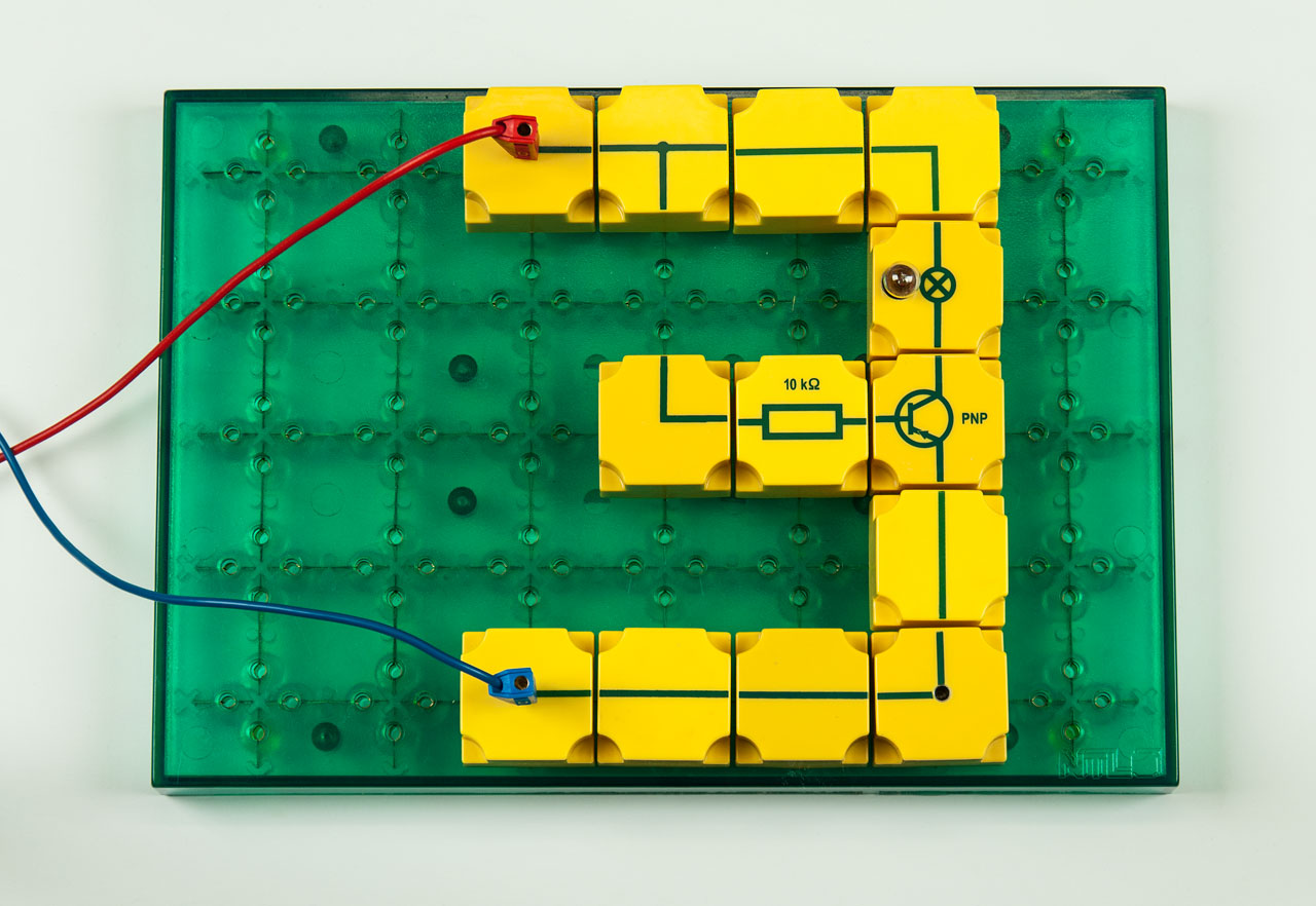
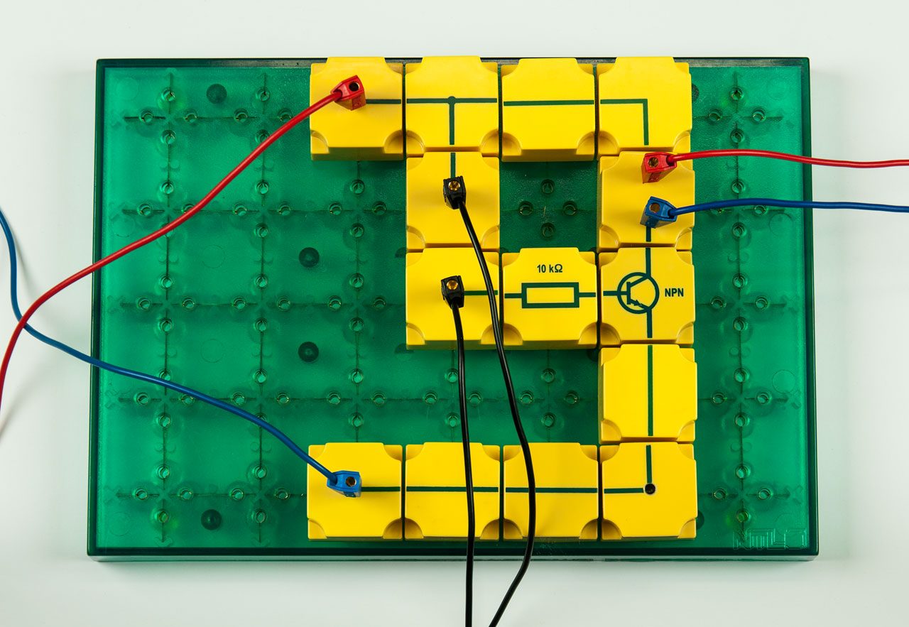
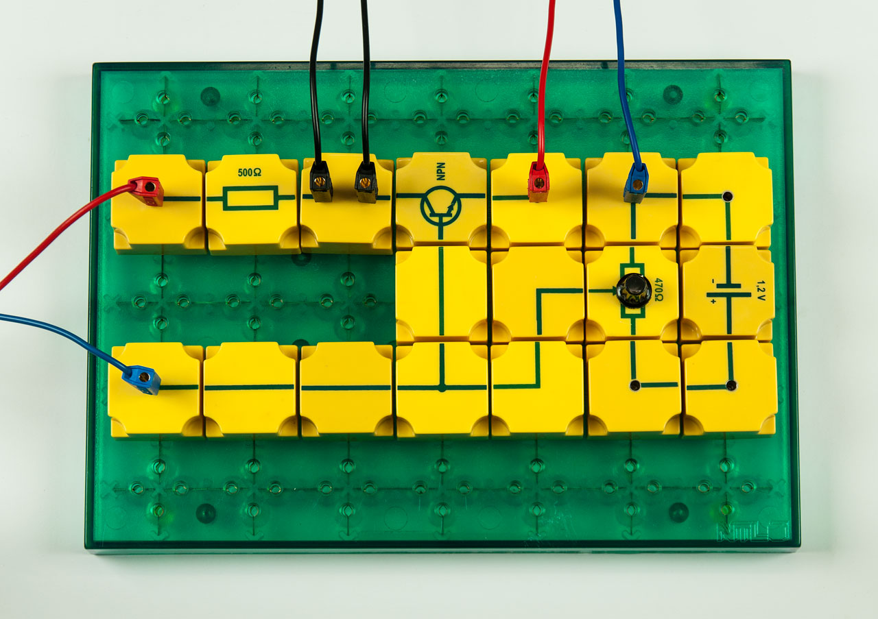
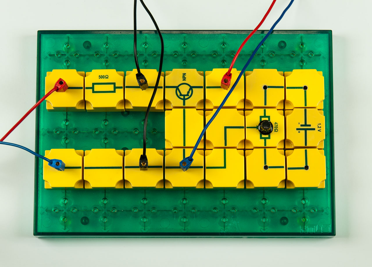
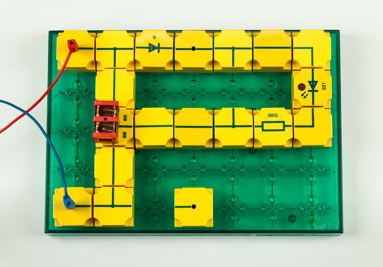
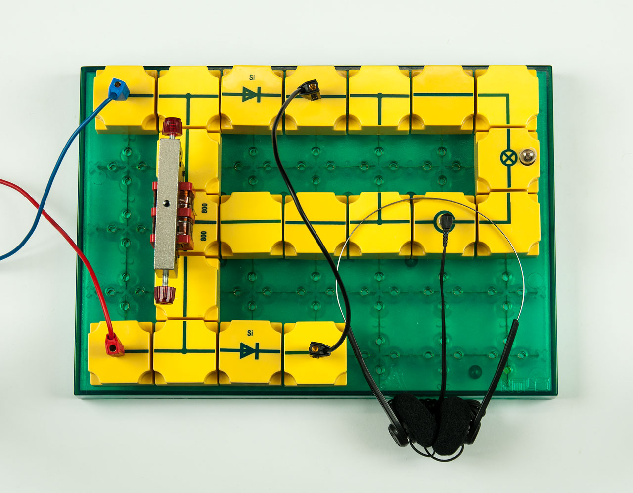
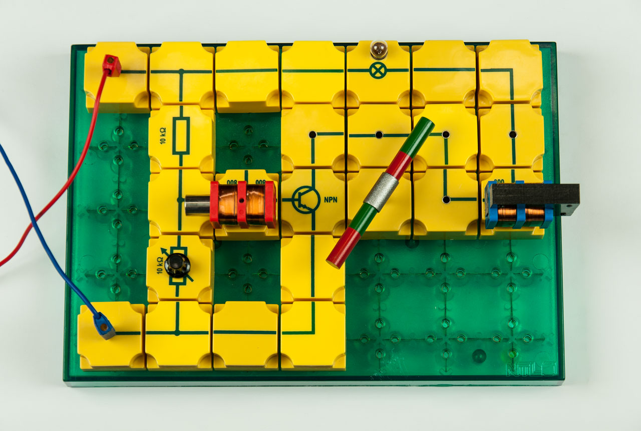
Student experiment equipment set for carrying out 109 experiments in the field of electricity - basics of electricity and comprehensive electronics on the topics:

  • Electricity
    • Basics (3 experiments)
    • Electrical resistance (18 experiments)
    • Work and power (1 experiment)
    • Electronics - Semiconductors (6 experiments)
  • Electronics
    • Diodes (10 experiments)
    • Transistors (21 experiments)
    • Capacitors (16 experiments)
    • Rectifier circuits (4 experiments)
    • Multivibrator circuits (8 experiments)
    • Oscillating circuits (5 experiments)
    • Amplifier circuits (9 experiments)
    • Logic circuits (8 experiments)
Outstanding features:
  • All components, all parts for all experiments in electronics and for numerous experiments on the basics of electrical circuits
    ⇒ Comprehensive and complete electronics
  • NTL plug-in block system SE - the yellow original
    ⇒ Circuit diagrams can be implemented 1:1 - ideal and important for understanding electrical circuits at the beginning of electrical teaching
    ⇒ Complex electronic circuits can also be implemented (➜ SEK Electronics supplement 1 and 2)
  • NTL-plug-in blocks are consisting of ABS plastic housing and transparent, screwed base plates
    ⇒ Electrical components are clearly identifiable and easy to replace
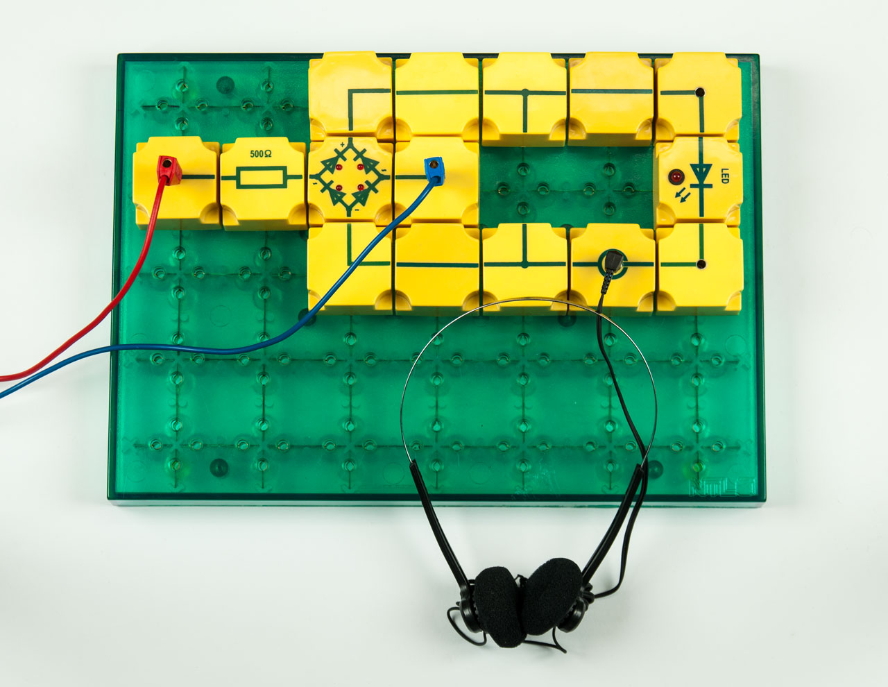
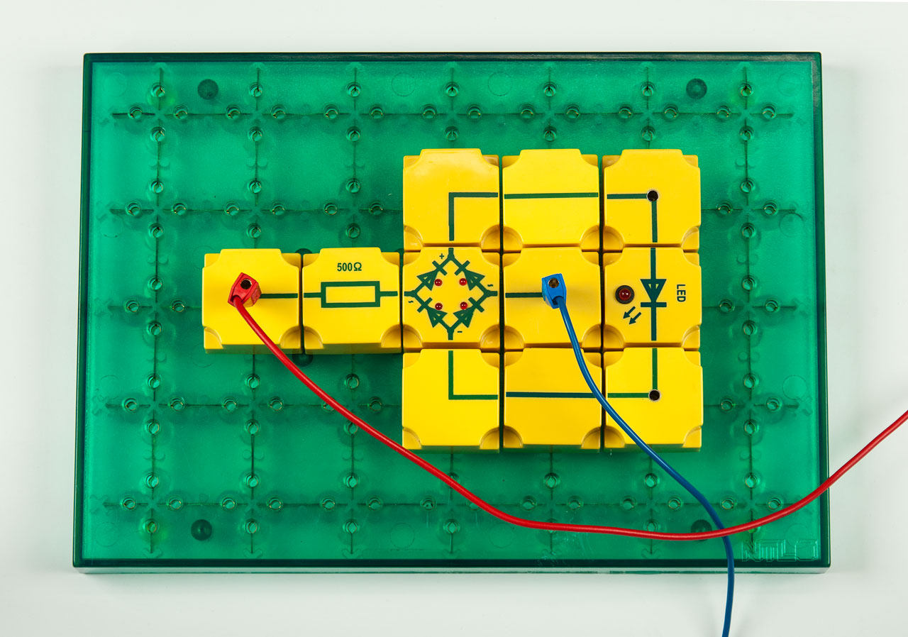
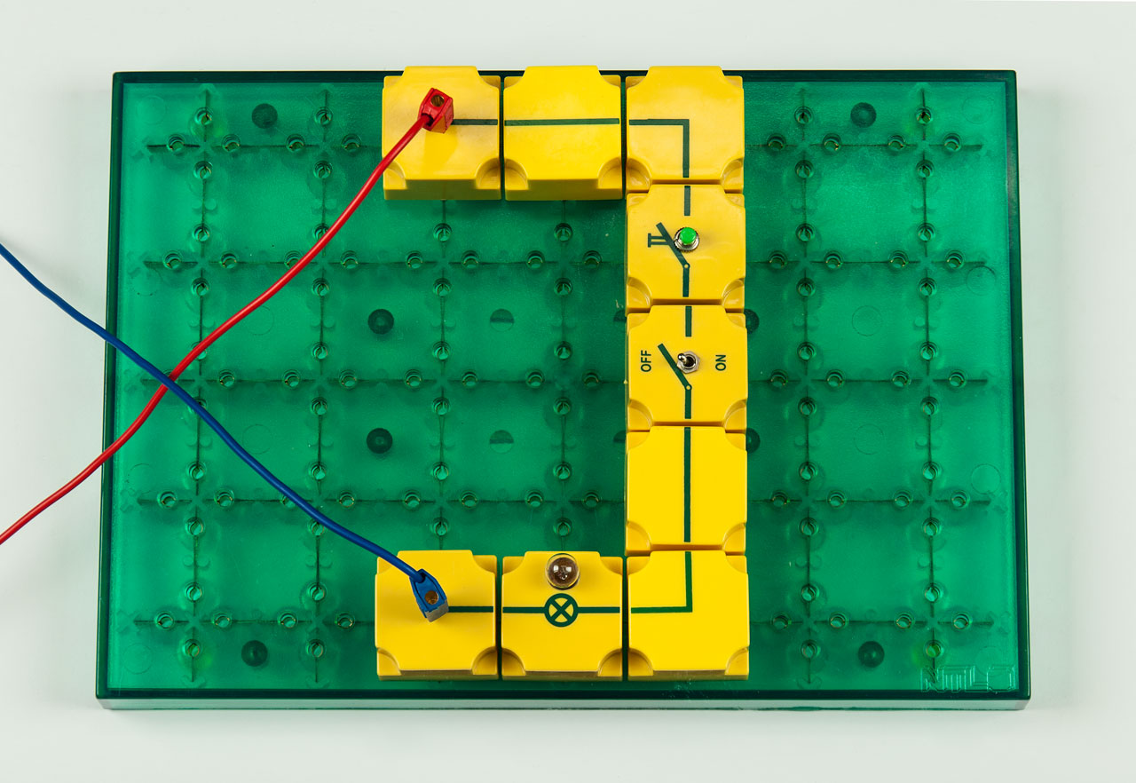
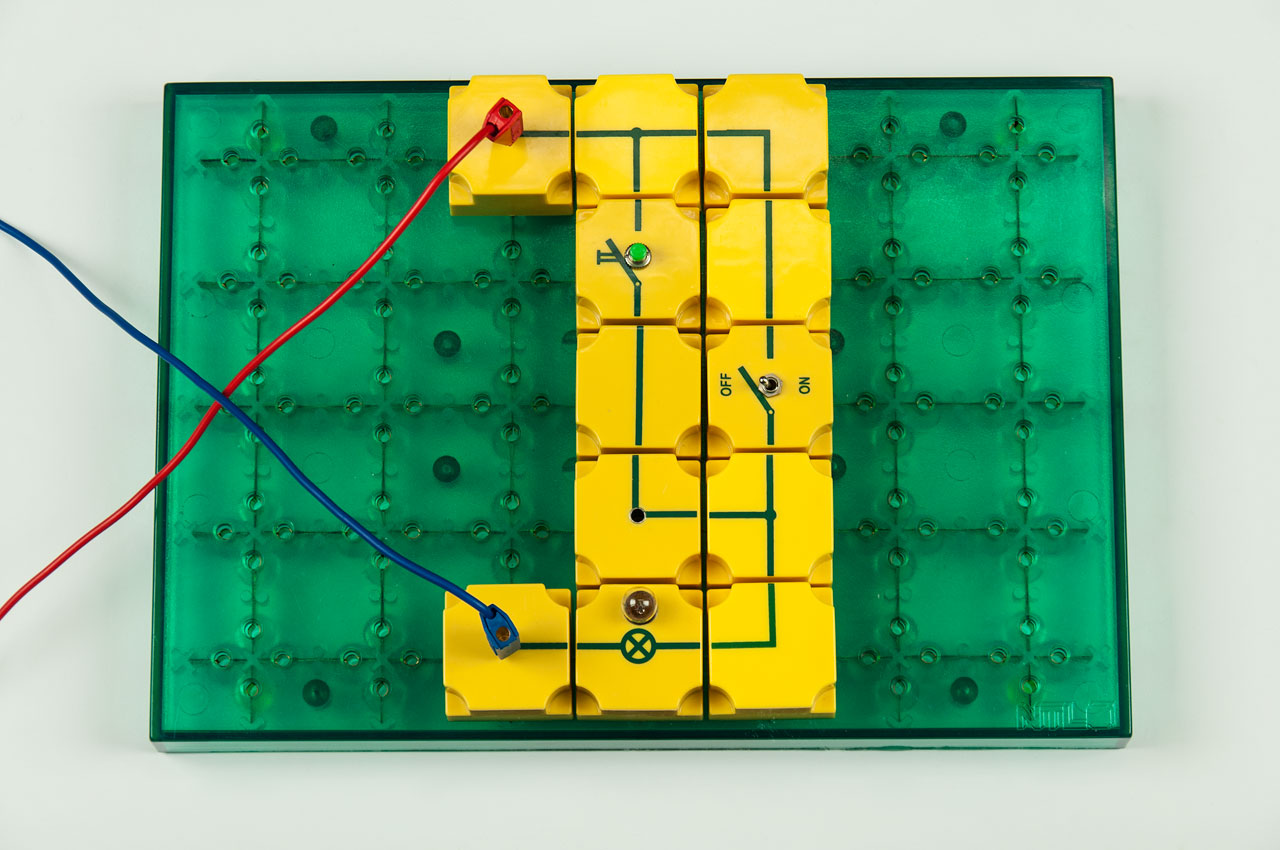
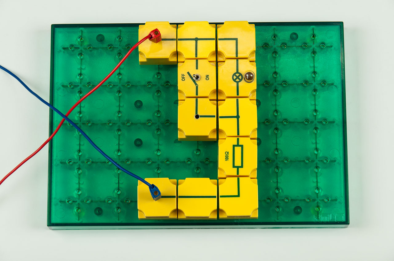
  • Each NTL plug-in module has its corresponding electrical component symbol printed on its top side
  • PIB bridge rectifier with 4 red LEDs: at a frequency of 0.5 Hz, the students can visually monitor the rectification
    ⇒ ideal for everyone as an introduction to electronics
The SEK student experiments system by NTL:
  • Topic-oriented structure and division according to physical sub-areas
  • All areas of physics are covered
  • Didactically and thematically sensible division of the sub-areas into several boxes
  • Each part in the student box can also be ordered separately and purchased individually if required
  • Student experiment instructions based on the curriculum and ideally matched to the composition of the boxes
  • Clear arrangement of the box contents: only 1 material layer in all boxes, without confusing intermediate shelves
  • Extremely stable storage boxes, non-slip stackable - and made from 100% recycled material
  • Molded plastic box inserts do not become brittle and have a long service life
The standard scope of delivery of our SEK contains:
  • Complete equipment set for a group of pupils
  • Storage box incl. lockable lid
  • Individually shaped plastic box insert
  • Clear box storage plan in the lid

The experiment manuals are not included with our SEK!

You will find the corresponding experiment manual in the accessories tab for this SEK.

Boxeneinlage für P9901-4M SEB Elektronik - gesamt (DEU)

P9901-4M Boxeneinlageplan (PDF) (166.42KB)

Plan for storage of all components for P9901-4M SEK Electronics complete (ENG)

P9901-4M Box insert plan (PDF) (165.93KB)

Charging guide for P3910-2K PIB battery (accu) 1.2V

P9901-4M Charging guide (PDF) (121.73KB)

Ladeanleitung für P3910-2K STB Batterie (Akku) 1,2V (DEU)

P9901-4M Ladeanleitung (PDF) (121.73KB)

Plán rozloženia pre P9901-4M ŽEM Elektronika - komplet (SK)

P9901-4M Plán uloženia (PDF) (444.29KB)

List of all experimental topics that can be carried out with this set (ENG)

P9901-4M Index experiments (PDF) (209.06KB)

Auflistung aller Versuchsthemen, welche mit diesem Set durchgeführt werden können (DEU)

P9901-4M Index Versuchsthemen (P (218.17KB)

The SEK Electronics - complete consists of the following contents:

Quantity Item no. Description
1x P3910-1A Plug-in panel, small NTL-Item: P3910-1A Plug-in panel, small
2x P3310-2E Connecting lead SE 25 cm, black NTL-Item: P3310-2E Connecting lead SE 25 cm, black
1x P3310-3A Connecting lead 50 cm, red, SE NTL-Item: P3310-3A Connecting lead 50 cm, red, SE
1x P3310-3B Connecting lead 50 cm, blue SE NTL-Item: P3310-3B Connecting lead 50 cm, blue SE
1x P3310-4A Connecting lead 75 cm, red, SE NTL-Item: P3310-4A Connecting lead 75 cm, red, SE
1x P3310-4B Connecting lead 75 cm, blue, SE NTL-Item: P3310-4B Connecting lead 75 cm, blue, SE
1x P3600-1A Solar cell, in plastic housing NTL-Item: P3600-1A Solar cell, in plastic housing
1x DW330-1M Microphone, dynamic NTL-Item: DW330-1M Microphone, dynamic
4x P3910-1B PIB connector NTL-Item: P3910-1B PIB connector
5x P3910-1C PIB wire, straight NTL-Item: P3910-1C PIB wire, straight
3x P3910-1D PIB wire, straight with socket NTL-Item: P3910-1D PIB wire, straight with socket
4x P3910-1E PIB wire, T-shaped NTL-Item: P3910-1E PIB wire, T-shaped
1x P3910-1F PIB wire, T-shaped, with socket NTL-Item: P3910-1F PIB wire, T-shaped, with socket
2x P3910-1G PIB wire, angled NTL-Item: P3910-1G PIB wire, angled
4x P3910-1H PIB wire, angled with socket NTL-Item: P3910-1H PIB wire, angled with socket
1x P3910-1J PIB wire, interrupted, with 2 sockets NTL-Item: P3910-1J PIB wire, interrupted, with 2 sockets
2x P3910-2A PIB lamp socket E 10 NTL-Item: P3910-2A PIB lamp socket E 10
2x P3910-2R PIB switch, ON/OFF NTL-Item: P3910-2R PIB switch, ON/OFF
1x P3910-2K PIB battery (accu) 1,2 V NTL-Item: P3910-2K PIB battery (accu) 1,2 V
1x P3910-1K PIB wire, straight with jack bush NTL-Item: P3910-1K PIB wire, straight with jack bush
1x P3910-3G PIB resistor 100 Ohm NTL-Item: P3910-3G PIB resistor 100 Ohm
1x P3910-3M PIB resistor 500 Ohm NTL-Item: P3910-3M PIB resistor 500 Ohm
1x P3910-3O PIB resistor 1 kOhm NTL-Item: P3910-3O PIB resistor 1 kOhm
1x P3910-3R PIB restistor 10 kOhm NTL-Item: P3910-3R PIB restistor 10 kOhm
1x P3910-3S PIB resistor 47 kOhm NTL-Item: P3910-3S PIB resistor 47 kOhm
1x P3910-5A PIB rheostat 10 kOhm NTL-Item: P3910-5A PIB rheostat 10 kOhm
1x P3910-5F PIB potentiometer 470 Ohm NTL-Item: P3910-5F PIB potentiometer 470 Ohm
1x P3910-4A PIB NTC resistor NTL-Item: P3910-4A PIB NTC resistor
1x P3910-4E PIB STB resistor NTL-Item: P3910-4E PIB STB resistor
1x P3910-4J PIB photo resistor (LDR) NTL-Item: P3910-4J PIB photo resistor (LDR)
1x P3910-4K PIB varistor (VDR) NTL-Item: P3910-4K PIB varistor (VDR)
1x P3910-6D PIB capacitor 0,1 µF NTL-Item: P3910-6D PIB capacitor 0,1 µF
1x P3910-6G PIB capacitor 1 µF NTL-Item: P3910-6G PIB capacitor 1 µF
1x P3910-6H PIB capacitor 2 µF NTL-Item: P3910-6H PIB capacitor 2 µF
1x P3910-6J PIB capacitor 10 µF NTL-Item: P3910-6J PIB capacitor 10 µF
1x P3910-6N PIB capacitor 100 µF NTL-Item: P3910-6N PIB capacitor 100 µF
1x P3910-6Q PIB capacitor 1000 µF NTL-Item: P3910-6Q PIB capacitor 1000 µF
2x P3910-7A PIB Si-diode NTL-Item: P3910-7A PIB Si-diode
1x P3910-7B PIB Ge-diode NTL-Item: P3910-7B PIB Ge-diode
1x P3910-7E PIB Zener diode 4,7 V NTL-Item: P3910-7E PIB Zener diode 4,7 V
2x P3910-7K PIB LED red NTL-Item: P3910-7K PIB LED red
1x P3910-7T PIB bridge rectifier NTL-Item: P3910-7T PIB bridge rectifier
1x P3910-8A PIB transistor NPN, base left NTL-Item: P3910-8A PIB transistor NPN, base left
1x P3910-8B PIB transistor NPN, base right NTL-Item: P3910-8B PIB transistor NPN, base right
1x P3910-8C PIB transistor PNP, base left NTL-Item: P3910-8C PIB transistor PNP, base left
1x P3911-2J PIB for coil 800 turns NTL-Item: P3911-2J PIB for coil 800 turns
1x P3911-2K PIB for coil with 2x800 turns NTL-Item: P3911-2K PIB for coil with 2x800 turns
1x P3911-2A PIB summer NTL-Item: P3911-2A PIB summer
1x P3911-2C Headphone, SE NTL-Item: P3911-2C Headphone, SE
1x P3911-2R Coil with 800 turns, SE, blue NTL-Item: P3911-2R Coil with 800 turns, SE, blue
1x P3911-2S Plug-in coil 2x800 turns, red NTL-Item: P3911-2S Plug-in coil 2x800 turns, red
1x P3911-1J Iron core , laminated, U-/I-core, clamping strap, SE NTL-Item: P3911-1J Iron core , laminated, U-/I-core, clamping strap, SE
2x P3320-1I Light bulb, 10V / 50mA, E10 NTL-Item: P3320-1I Light bulb, 10V / 50mA, E10
1x P3410-2M Bearing bush for cylindrical magnets NTL-Item: P3410-2M Bearing bush for cylindrical magnets
2x P3410-1K Magnet , AINiCo, D10 mm,L50 mm NTL-Item: P3410-1K Magnet , AINiCo, D10 mm,L50 mm
1x P3911-1K Iron core solid, L 56 mm NTL-Item: P3911-1K Iron core solid, L 56 mm
1x P3911-3F Plug pin with needle NTL-Item: P3911-3F Plug pin with needle
2x P3310-1A Crocodile clip, plain metal NTL-Item: P3310-1A Crocodile clip, plain metal
2x P3911-3D Crocodile clip with plug NTL-Item: P3911-3D Crocodile clip with plug
1x P7906-4DS Box insert "soft", plug-in board and cables, SE NTL-Item: P7906-4DS Box insert "soft", plug-in board and cables, SE
1x P7906-4FS Insert "soft", micro and headphones, SE NTL-Item: P7906-4FS Insert "soft", micro and headphones, SE
1x P7906-4M Box insert Electronics, complete, SE NTL-Item: P7906-4M Box insert Electronics, complete, SE
1x P7806-1G Storage box - lid, II, with fleece NTL-Item: P7806-1G Storage box - lid, II, with fleece
1x Box insert plan
2x Labels
1. Basics
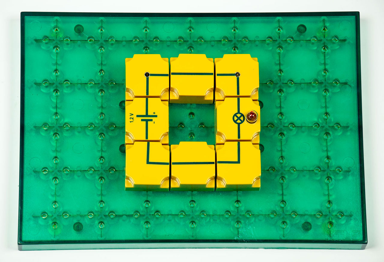
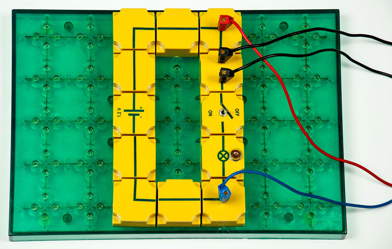
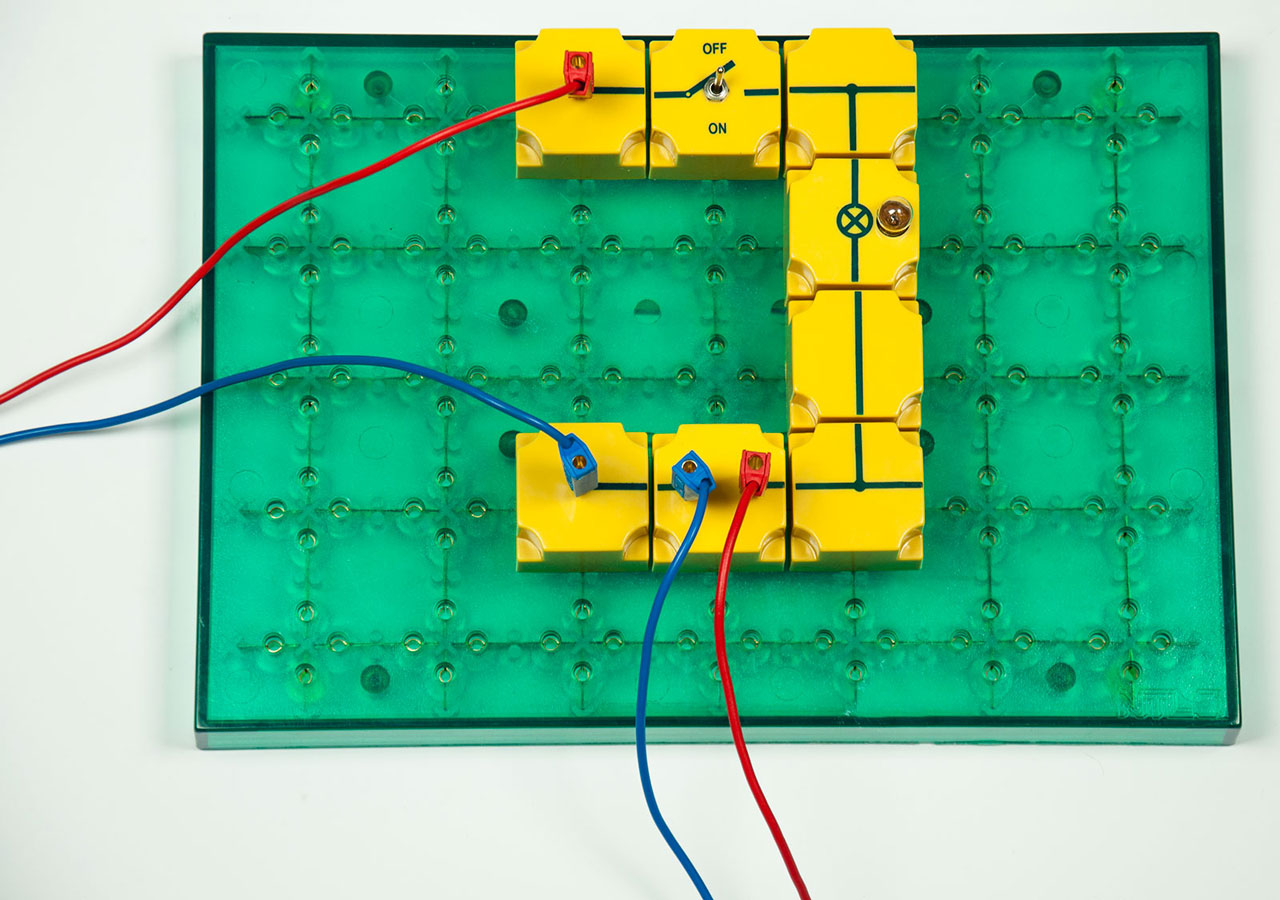
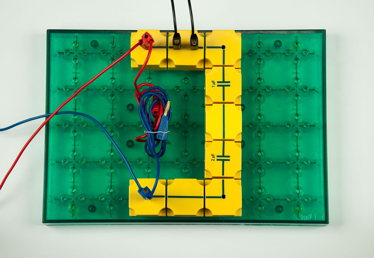
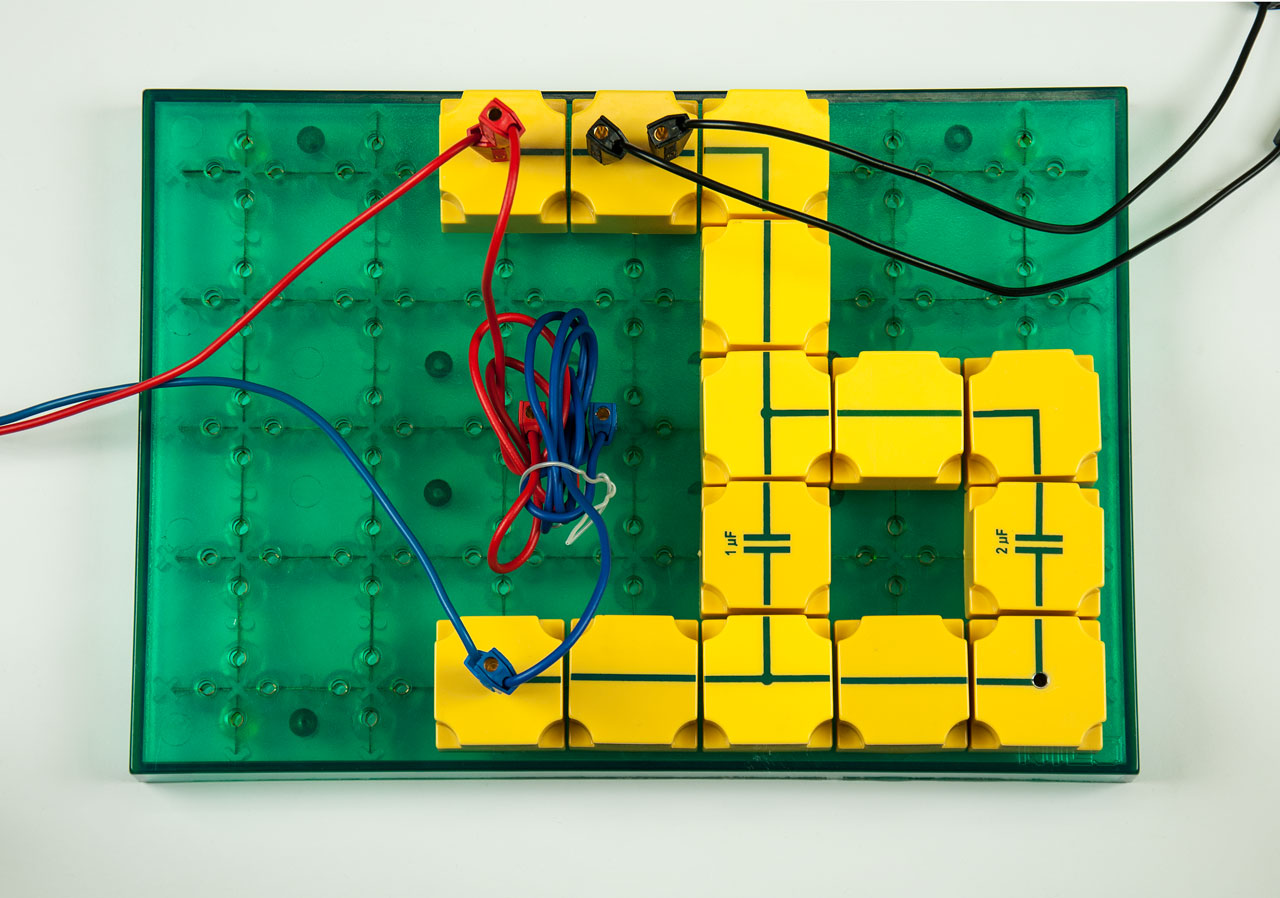
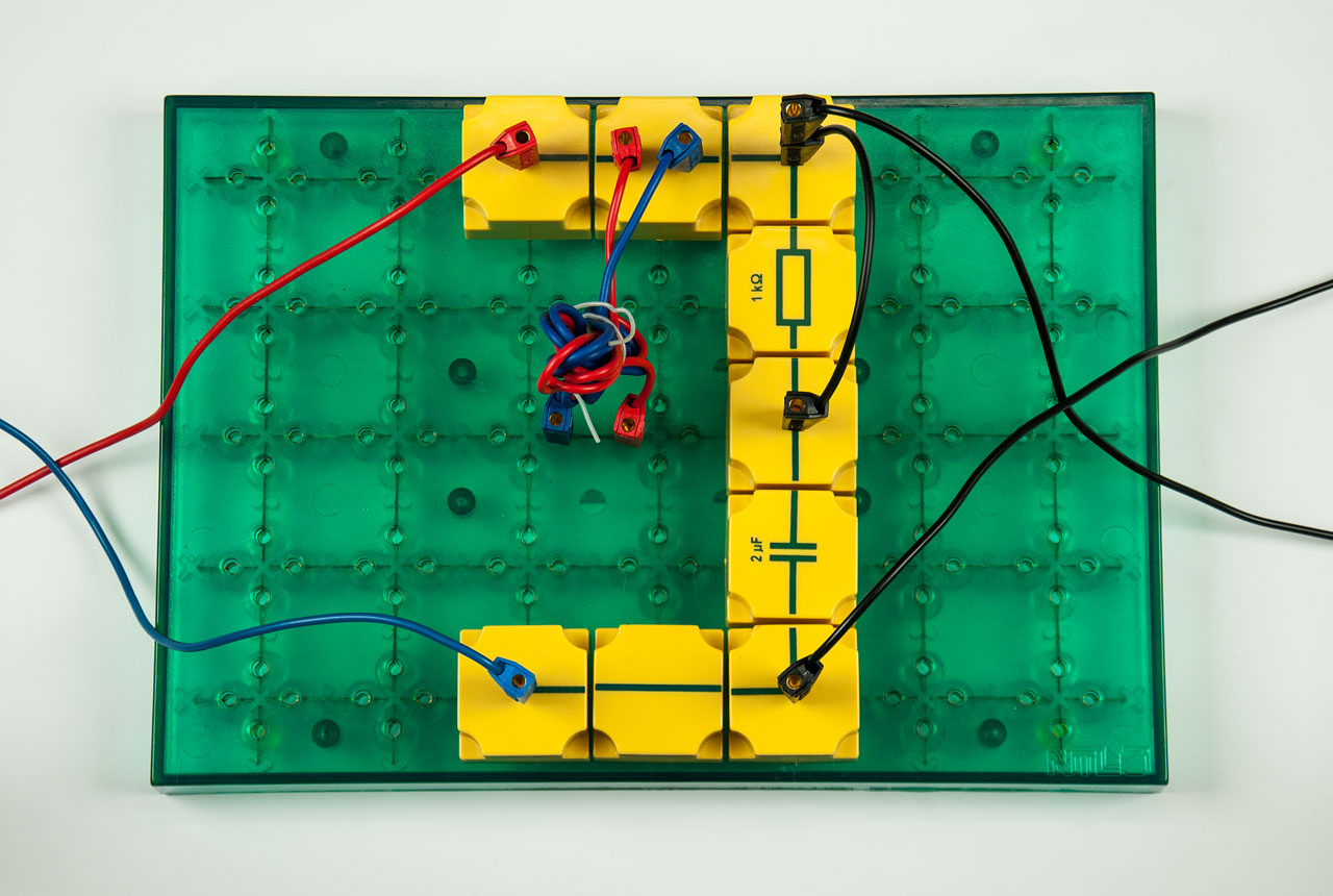
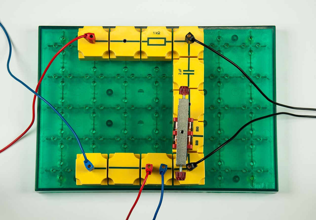
ELS 1.1 The electrical circuit Photo of the experimental setup: ELS 1.1 The electrical circuit Symbolic image of a PDF document
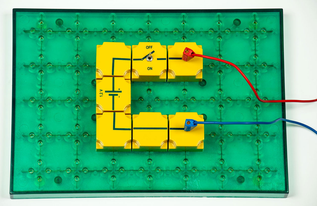
ELS 1.3 Voltage Photo of the experimental setup: ELS 1.3 Voltage Symbolic image of a PDF document
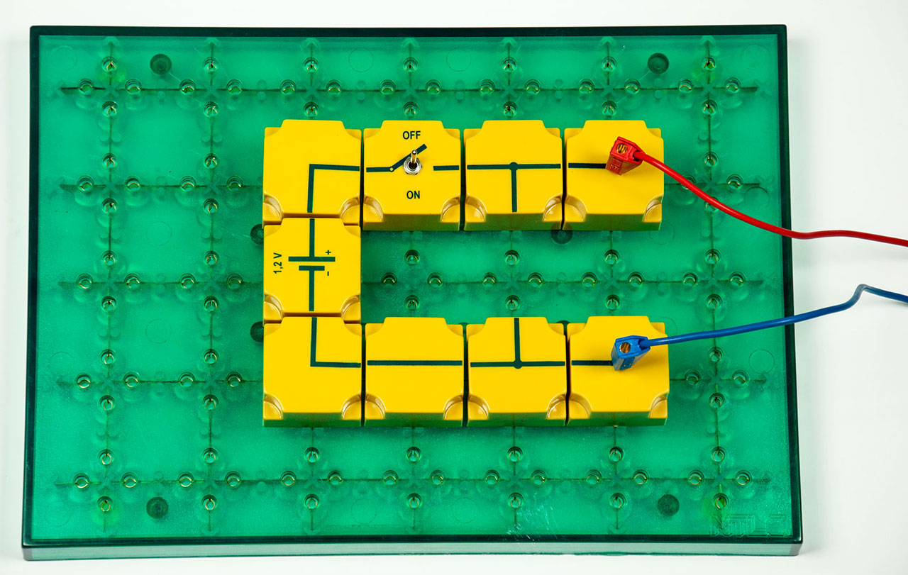
ELS 1.5 Parallel connection of voltage sources Photo of the experimental setup: ELS 1.5 Parallel connection of voltage sources Symbolic image of a PDF document
2. Electrical resistance
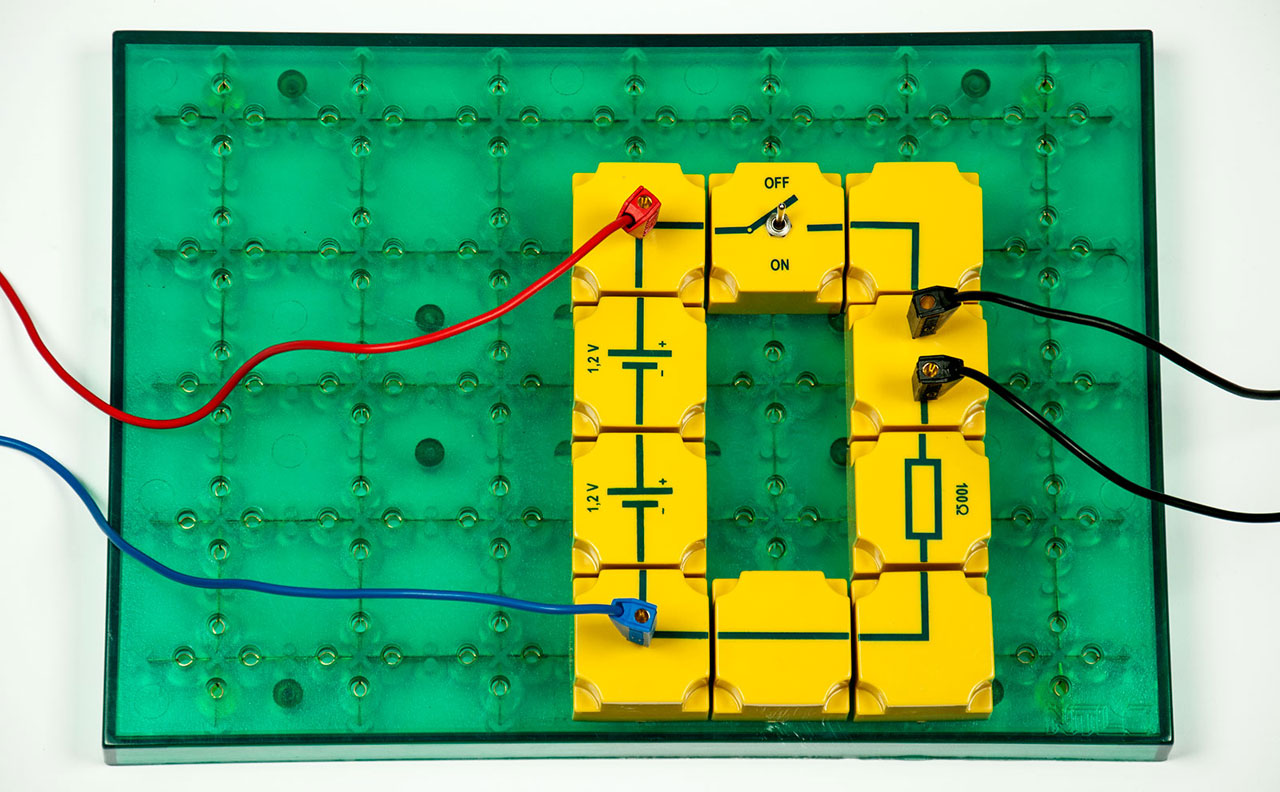
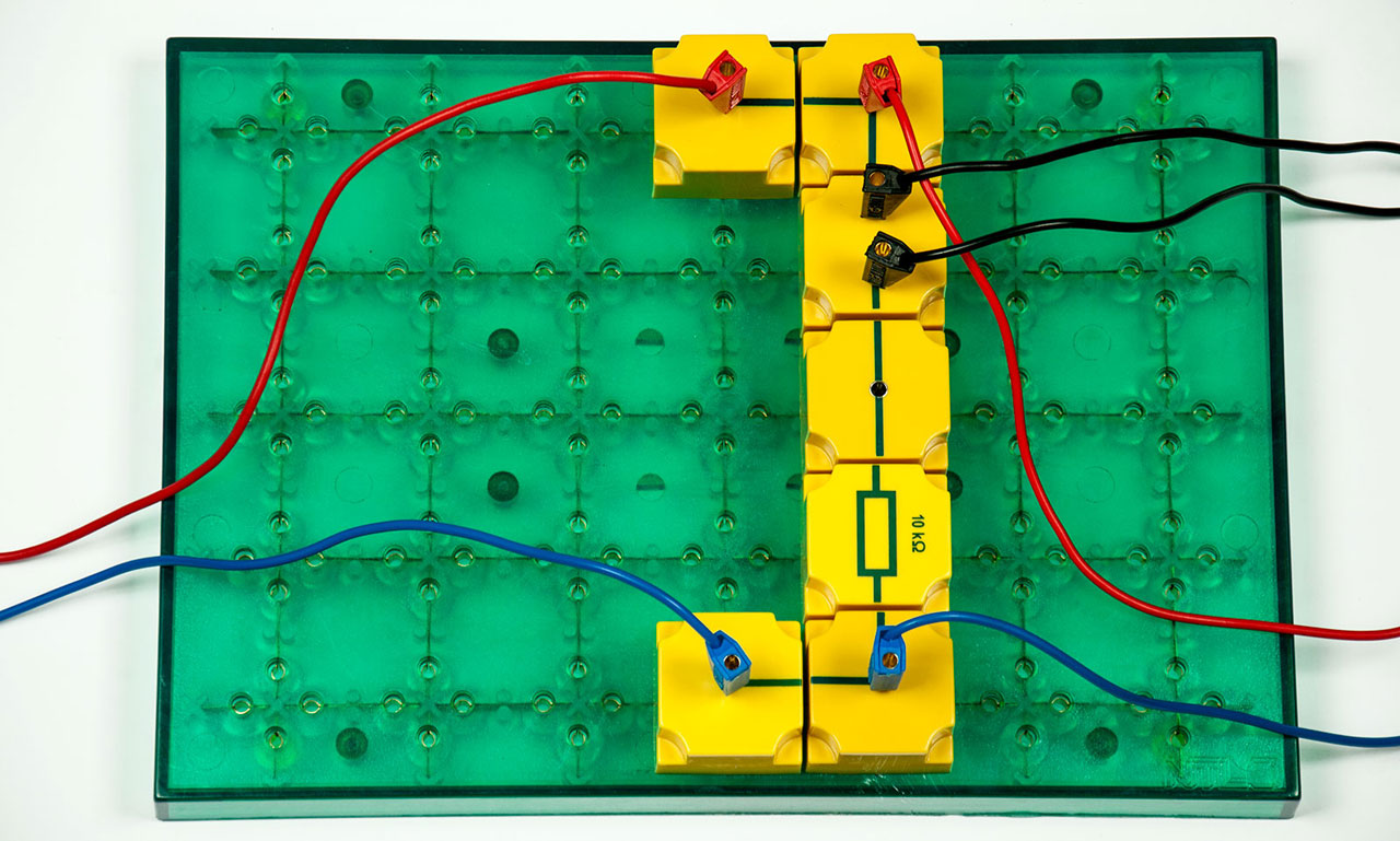
ELS 2.2 Application of Ohm s Law Photo of the experimental setup: ELS 2.2 Application of Ohm s Law Symbolic image of a PDF document
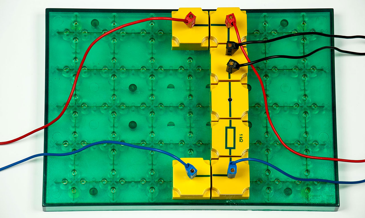
ELS 2.4 Ohmic resistor Photo of the experimental setup: ELS 2.4 Ohmic resistor Symbolic image of a PDF document
ELS 2.5 An incandescent lamp is not an ohmic resistor Photo of the experimental setup: ELS 2.5 An incandescent lamp is not an ohmic resistor Symbolic image of a PDF document
ELS 2.6 Serial connection of incandescent lamps Photo of the experimental setup: ELS 2.6 Serial connection of incandescent lamps Symbolic image of a PDF document
ELS 2.7 Serial connection of ohmic resistors Photo of the experimental setup: ELS 2.7 Serial connection of ohmic resistors Symbolic image of a PDF document
ELS 2.8 Voltage division Photo of the experimental setup: ELS 2.8 Voltage division Symbolic image of a PDF document
ELS 2.8.1 Sliding resistor Photo of the experimental setup: ELS 2.8.1 Sliding resistor Symbolic image of a PDF document
ELS 2.9 Parallel connection of incandescent lamps Photo of the experimental setup: ELS 2.9 Parallel connection of incandescent lamps Symbolic image of a PDF document
ELS 2.10 Parallel connection of ohmic resistors Photo of the experimental setup: ELS 2.10 Parallel connection of ohmic resistors Symbolic image of a PDF document
ELS 2.11 Resistors in parallel/series circuits Photo of the experimental setup: ELS 2.11 Resistors in parallel/series circuits Symbolic image of a PDF document
ELS 2.12 Why are voltage sources connected in parallel? Photo of the experimental setup: ELS 2.12 Why are voltage sources connected in parallel? Symbolic image of a PDF document
ELS 2.13.1 Dimming by means of a potentiometer Photo of the experimental setup: ELS 2.13.1 Dimming by means of a potentiometer Symbolic image of a PDF document
ELS 2.13.2 Unloaded potentiometer Photo of the experimental setup: ELS 2.13.2 Unloaded potentiometer Symbolic image of a PDF document
ELS 2.13.3 Loaded potentiometer Photo of the experimental setup: ELS 2.13.3 Loaded potentiometer Symbolic image of a PDF document
ELS 2.14 Internal resistance of voltage sources (terminal voltage) Photo of the experimental setup: ELS 2.14 Internal resistance of voltage sources (terminal voltage) Symbolic image of a PDF document
ELS 2.15 Internal resistance of a voltmeter Photo of the experimental setup: ELS 2.15 Internal resistance of a voltmeter Symbolic image of a PDF document
ELS 2.16 Internal resistance of an ammeter Photo of the experimental setup: ELS 2.16 Internal resistance of an ammeter Symbolic image of a PDF document
ELS 2.17 Expansion of the measuring range of a voltmeter Photo of the experimental setup: ELS 2.17 Expansion of the measuring range of a voltmeter Symbolic image of a PDF document
4. Work and power
ELS 4.1 The power of incandescent lamps Photo of the experimental setup: ELS 4.1 The power of incandescent lamps Symbolic image of a PDF document
1. Semiconductors
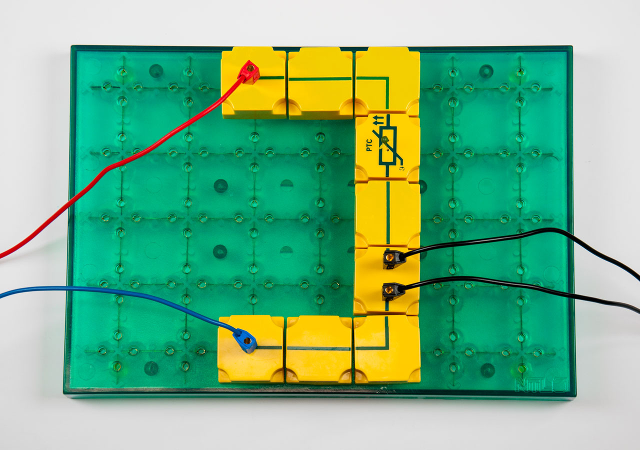
EOS 1.1 PTC-resistor Photo of the experimental setup: EOS 1.1 PTC-resistor Symbolic image of a PDF document
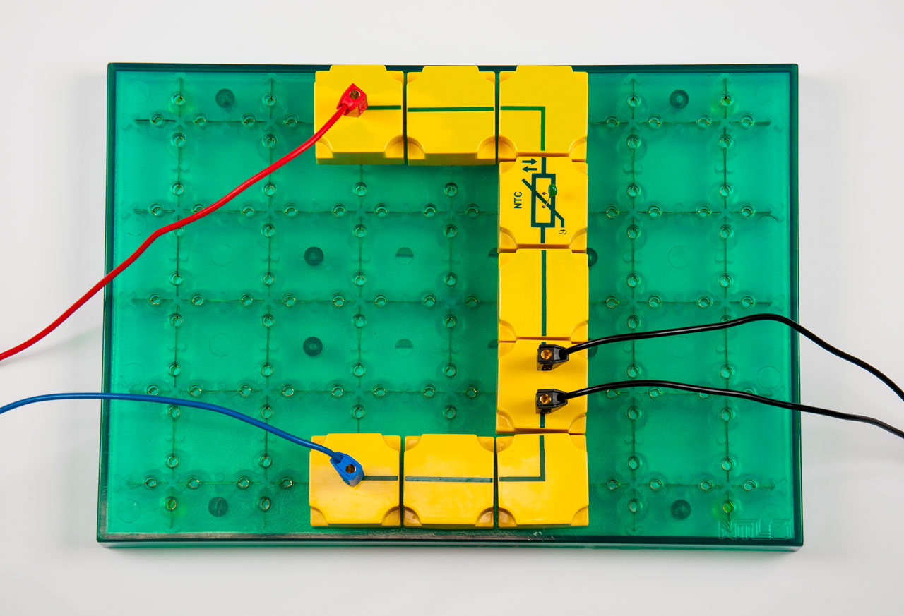
EOS 1.2 NTC-resistor Photo of the experimental setup: EOS 1.2 NTC-resistor Symbolic image of a PDF document
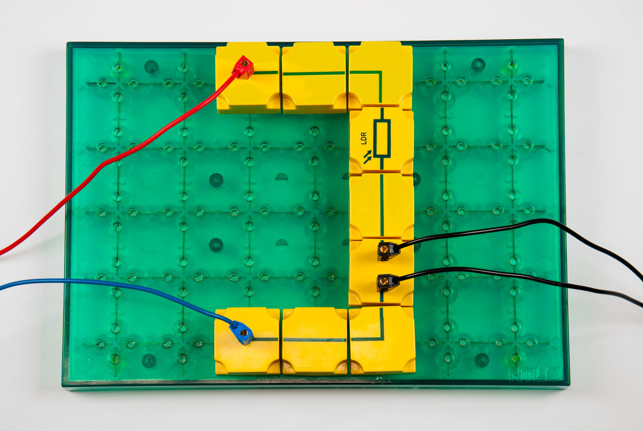
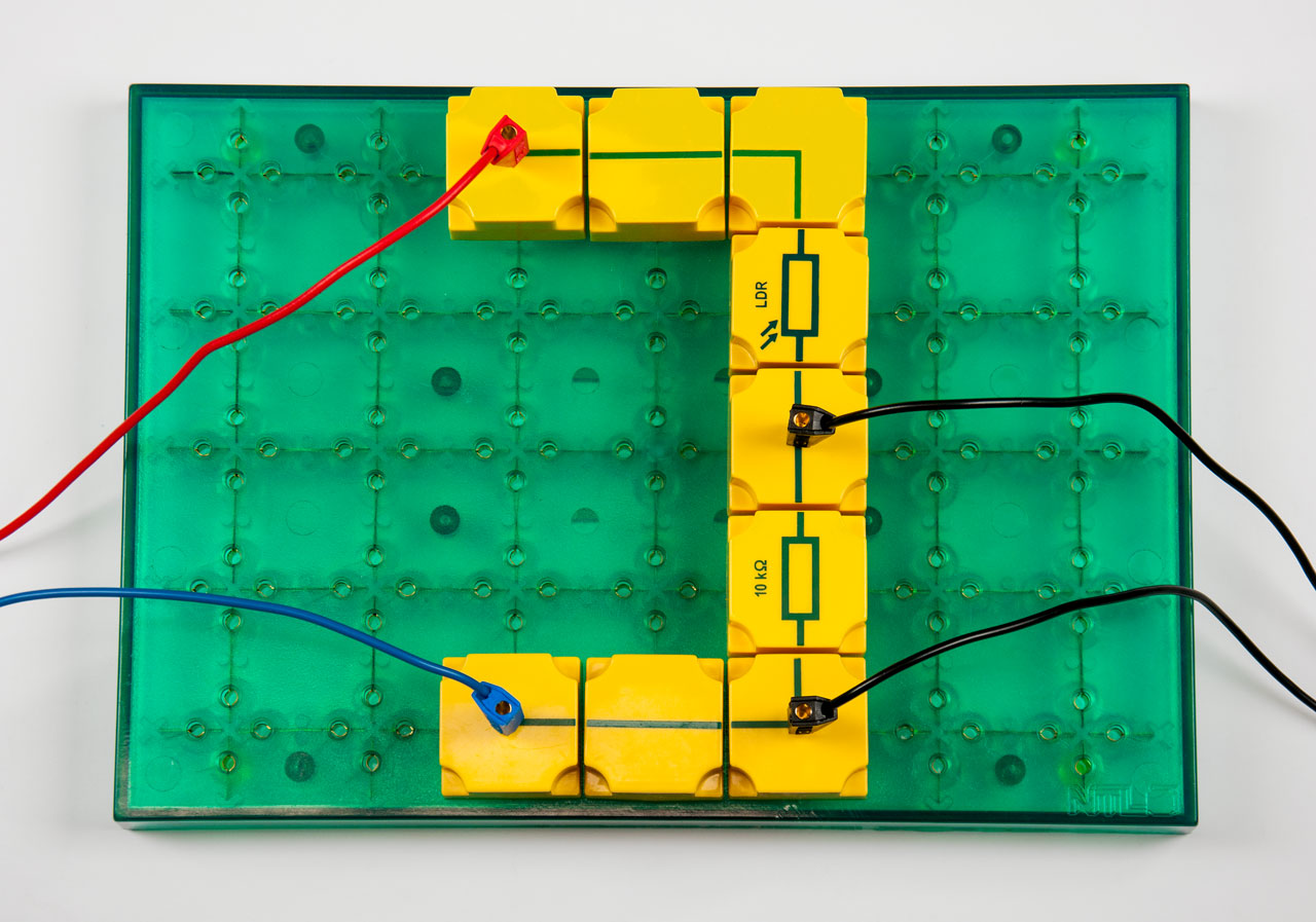
EOS 1.3 Light dependent resistor (LDR) Photo of the experimental setup: EOS 1.3 Light dependent resistor (LDR) Symbolic image of a PDF document
EOS 1.4 Measuring the luminous intensity Photo of the experimental setup: EOS 1.4 Measuring the luminous intensity Symbolic image of a PDF document
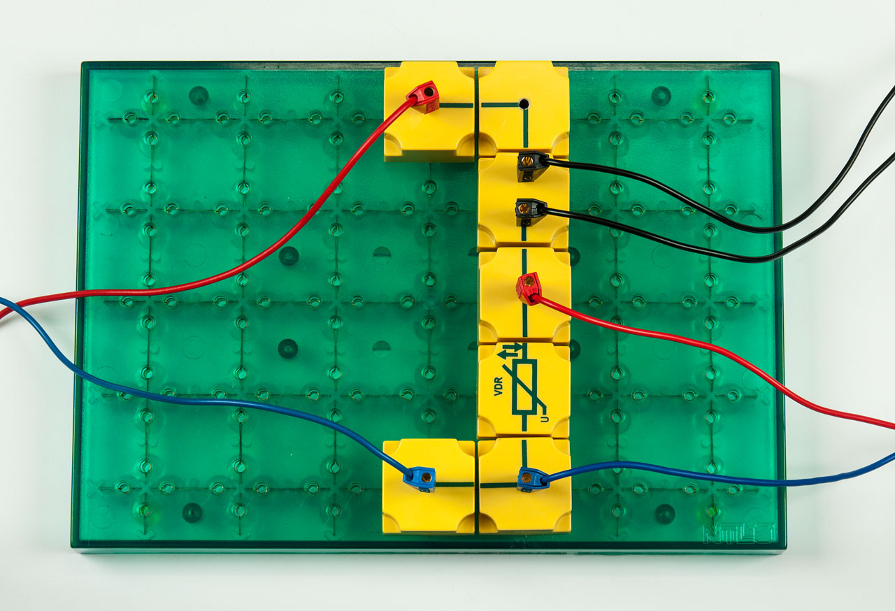
EOS 1.5 VDR-resistor Photo of the experimental setup: EOS 1.5 VDR-resistor Symbolic image of a PDF document
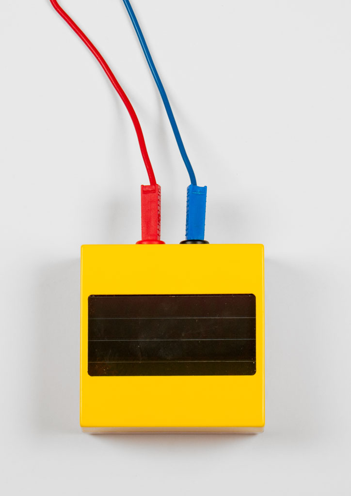
EOS 1.6 Solar cell Photo of the experimental setup: EOS 1.6 Solar cell Symbolic image of a PDF document
2. Diodes
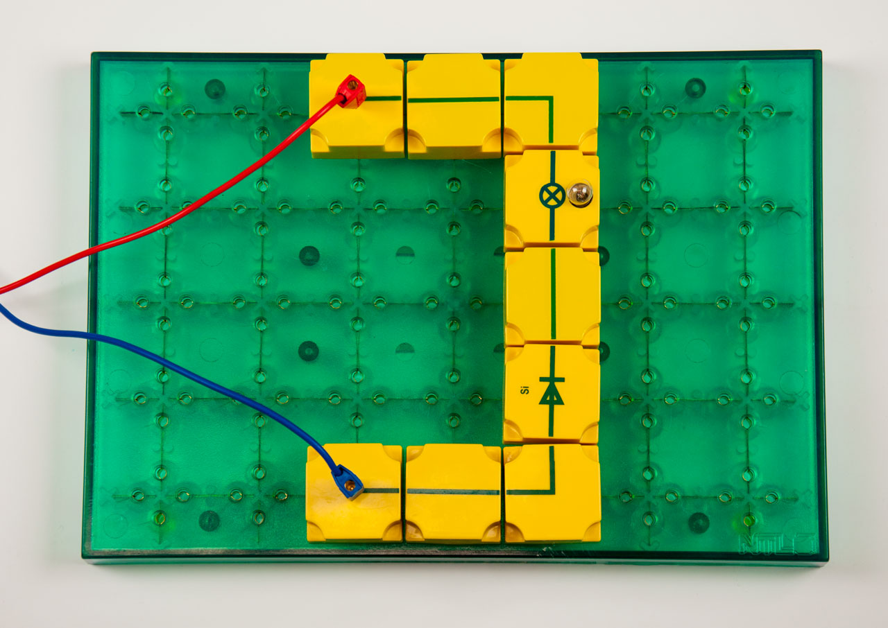
EOS 2.1 Silicon diode Photo of the experimental setup: EOS 2.1 Silicon diode Symbolic image of a PDF document
EOS 2.2 Forward voltage of a silicon diode Photo of the experimental setup: EOS 2.2 Forward voltage of a silicon diode Symbolic image of a PDF document
EOS 2.2.1 Characteristic lines of semiconductor diodes Photo of the experimental setup: EOS 2.2.1 Characteristic lines of semiconductor diodes Symbolic image of a PDF document
EOS 2.3 Diodes protect meters Photo of the experimental setup: EOS 2.3 Diodes protect meters Symbolic image of a PDF document
EOS 2.4 Light-emitting diode (LED) Photo of the experimental setup: EOS 2.4 Light-emitting diode (LED) Symbolic image of a PDF document
EOS 2.4.1 Forward voltage of an LED Photo of the experimental setup: EOS 2.4.1 Forward voltage of an LED Symbolic image of a PDF document
EOS 2.5 Indicators of polarity Photo of the experimental setup: EOS 2.5 Indicators of polarity Symbolic image of a PDF document
EOS 2.5.1 Indicators of polarity at A.C. with variable frequency Photo of the experimental setup: EOS 2.5.1 Indicators of polarity at A.C. with variable frequency Symbolic image of a PDF document
EOS 2.6 Zener diodes Photo of the experimental setup: EOS 2.6 Zener diodes Symbolic image of a PDF document
EOS 2.7 Stabilizing of voltage Photo of the experimental setup: EOS 2.7 Stabilizing of voltage Symbolic image of a PDF document
3. Transistors
EOS 3.1 Does a transistor consist of two diodes? Photo of the experimental setup: EOS 3.1 Does a transistor consist of two diodes? Symbolic image of a PDF document
EOS 3.1.1 How does a PNP-transistor behave? Photo of the experimental setup: EOS 3.1.1 How does a PNP-transistor behave? Symbolic image of a PDF document
EOS 3.2 Base current makes collector current possible (NPN-transistor) Photo of the experimental setup: EOS 3.2 Base current makes collector current possible (NPN-transistor) Symbolic image of a PDF document
EOS 3.2.1 Base current allows current at collector (PNP-transistor) Photo of the experimental setup: EOS 3.2.1 Base current allows current at collector (PNP-transistor) Symbolic image of a PDF document
EOS 3.3 The transistors as an amplifier Photo of the experimental setup: EOS 3.3 The transistors as an amplifier Symbolic image of a PDF document
EOS 3.3.1 Base connection (current amplification) Photo of the experimental setup: EOS 3.3.1 Base connection (current amplification) Symbolic image of a PDF document
EOS 3.3.2 Base connection (voltage amplification) Photo of the experimental setup: EOS 3.3.2 Base connection (voltage amplification) Symbolic image of a PDF document
EOS 3.3.3 Collector connection (current amplification) Photo of the experimental setup: EOS 3.3.3 Collector connection (current amplification) Symbolic image of a PDF document
EOS 3.3.4 Collector connection (voltage amplification) Photo of the experimental setup: EOS 3.3.4 Collector connection (voltage amplification) Symbolic image of a PDF document
EOS 3.3.5 Emittor connection (current amplification) Photo of the experimental setup: EOS 3.3.5 Emittor connection (current amplification) Symbolic image of a PDF document
EOS 3.3.6 Transfer characteristic of a NPN-transistor Photo of the experimental setup: EOS 3.3.6 Transfer characteristic of a NPN-transistor Symbolic image of a PDF document
EOS 3.3.7 Transfer characteristic of a PNP-transistor Photo of the experimental setup: EOS 3.3.7 Transfer characteristic of a PNP-transistor Symbolic image of a PDF document
EOS 3.3.8 Adjustment of the operating point Photo of the experimental setup: EOS 3.3.8 Adjustment of the operating point Symbolic image of a PDF document
EOS 3.3.9 Amplification free distortion due to base quiescent current Photo of the experimental setup: EOS 3.3.9 Amplification free distortion due to base quiescent current Symbolic image of a PDF document
EOS 3.4 Light triggered alarm Photo of the experimental setup: EOS 3.4 Light triggered alarm Symbolic image of a PDF document
EOS 3.5 Base voltage divider Photo of the experimental setup: EOS 3.5 Base voltage divider Symbolic image of a PDF document
EOS 3.6 Construction of a burglar alarm by means of trip wire Photo of the experimental setup: EOS 3.6 Construction of a burglar alarm by means of trip wire Symbolic image of a PDF document
EOS 3.7 Automatic illumination Photo of the experimental setup: EOS 3.7 Automatic illumination Symbolic image of a PDF document
EOS 3.8 Alarm by means of light barriers Photo of the experimental setup: EOS 3.8 Alarm by means of light barriers Symbolic image of a PDF document
EOS 3.9 Fire alarm Photo of the experimental setup: EOS 3.9 Fire alarm Symbolic image of a PDF document
EOS 3.10 Electric thermometer Photo of the experimental setup: EOS 3.10 Electric thermometer Symbolic image of a PDF document
4. Capacitors
EOS 4.1 A storage for electric charges Photo of the experimental setup: EOS 4.1 A storage for electric charges Symbolic image of a PDF document
EOS 4.2 A capacitor supplies base current Photo of the experimental setup: EOS 4.2 A capacitor supplies base current Symbolic image of a PDF document
EOS 4.3 Capacitance Photo of the experimental setup: EOS 4.3 Capacitance Symbolic image of a PDF document
EOS 4.3.1 Time switch Photo of the experimental setup: EOS 4.3.1 Time switch Symbolic image of a PDF document
EOS 4.4 A capacitor blocks D.C Photo of the experimental setup: EOS 4.4 A capacitor blocks D.C Symbolic image of a PDF document
EOS 4.5 Half-wave rectification Photo of the experimental setup: EOS 4.5 Half-wave rectification Symbolic image of a PDF document
EOS 4.6 Smoothing of rectified voltage Photo of the experimental setup: EOS 4.6 Smoothing of rectified voltage Symbolic image of a PDF document
EOS 4.7 Capacitors as A.C. resistance Photo of the experimental setup: EOS 4.7 Capacitors as A.C. resistance Symbolic image of a PDF document
EOS 4.7.1 Capacitive resistance at an A.C. of 50 Hz Photo of the experimental setup: EOS 4.7.1 Capacitive resistance at an A.C. of 50 Hz Symbolic image of a PDF document
EOS 4.7.2 Capacitive resistance Photo of the experimental setup: EOS 4.7.2 Capacitive resistance Symbolic image of a PDF document
EOS 4.8 Charged capacitors connected in series Photo of the experimental setup: EOS 4.8 Charged capacitors connected in series Symbolic image of a PDF document
EOS 4.9 Capacitors connected in series (determination of capacitance) Photo of the experimental setup: EOS 4.9 Capacitors connected in series (determination of capacitance) Symbolic image of a PDF document
EOS 4.10 Capacitors connected in parallel Photo of the experimental setup: EOS 4.10 Capacitors connected in parallel Symbolic image of a PDF document
EOS 4.11 A.C. resistors connected in series Photo of the experimental setup: EOS 4.11 A.C. resistors connected in series Symbolic image of a PDF document
EOS 4.12 Ohmic resistors, coil and capacitor in an A.C. circuit Photo of the experimental setup: EOS 4.12 Ohmic resistors, coil and capacitor in an A.C. circuit Symbolic image of a PDF document
EOS 4.13 Filter Photo of the experimental setup: EOS 4.13 Filter Symbolic image of a PDF document
5. Rectifier circuits
EOS 5.1 Principle of full-wave rectifying (mid-point tapping) Photo of the experimental setup: EOS 5.1 Principle of full-wave rectifying (mid-point tapping) Symbolic image of a PDF document
EOS 5.2 Application of full-wave rectifying Photo of the experimental setup: EOS 5.2 Application of full-wave rectifying Symbolic image of a PDF document
EOS 5.3 Bridge connection Photo of the experimental setup: EOS 5.3 Bridge connection Symbolic image of a PDF document
EOS 5.3.1 Bridge connection at A.C. with variable frequency Photo of the experimental setup: EOS 5.3.1 Bridge connection at A.C. with variable frequency Symbolic image of a PDF document
6. Multivibrator circuits
EOS 6.1 Bistable multivibrator Photo of the experimental setup: EOS 6.1 Bistable multivibrator Symbolic image of a PDF document
EOS 6.2 Discharging of a capacitor Photo of the experimental setup: EOS 6.2 Discharging of a capacitor Symbolic image of a PDF document
EOS 6.3 A capacitor prevents base current Photo of the experimental setup: EOS 6.3 A capacitor prevents base current Symbolic image of a PDF document
EOS 6.4 Monostable multivibrator Photo of the experimental setup: EOS 6.4 Monostable multivibrator Symbolic image of a PDF document
EOS 6.5 Flashing circuit Photo of the experimental setup: EOS 6.5 Flashing circuit Symbolic image of a PDF document
EOS 6.6 Multivibrator music Photo of the experimental setup: EOS 6.6 Multivibrator music Symbolic image of a PDF document
EOS 6.7 Music controlled by light Photo of the experimental setup: EOS 6.7 Music controlled by light Symbolic image of a PDF document
EOS 6.7.1 Music controlled by temperature Photo of the experimental setup: EOS 6.7.1 Music controlled by temperature Symbolic image of a PDF document
7. Oscillating circuits
EOS 7.1 Principle of a resonant circuit Photo of the experimental setup: EOS 7.1 Principle of a resonant circuit Symbolic image of a PDF document
EOS 7.1.1 Parallel resonant circuit Photo of the experimental setup: EOS 7.1.1 Parallel resonant circuit Symbolic image of a PDF document
EOS 7.1.2 Acceptor circuit Photo of the experimental setup: EOS 7.1.2 Acceptor circuit Symbolic image of a PDF document
EOS 7.2 Continuous oscillations Photo of the experimental setup: EOS 7.2 Continuous oscillations Symbolic image of a PDF document
EOS 7.3 LC-music Photo of the experimental setup: EOS 7.3 LC-music Symbolic image of a PDF document
8. Amplifier circuits
EOS 8.1 The resistance of human bodies Photo of the experimental setup: EOS 8.1 The resistance of human bodies Symbolic image of a PDF document
EOS 8.1.1 A transistor step controls a second step Photo of the experimental setup: EOS 8.1.1 A transistor step controls a second step Symbolic image of a PDF document
EOS 8.1.2 Alarm at failure of the heating Photo of the experimental setup: EOS 8.1.2 Alarm at failure of the heating Symbolic image of a PDF document
EOS 8.2 Automatic level measuring Photo of the experimental setup: EOS 8.2 Automatic level measuring Symbolic image of a PDF document
EOS 8.3 Lie detector Photo of the experimental setup: EOS 8.3 Lie detector Symbolic image of a PDF document
EOS 8.4 Microphone amplifier Photo of the experimental setup: EOS 8.4 Microphone amplifier Symbolic image of a PDF document
EOS 8.5 Sum and difference amplifier Photo of the experimental setup: EOS 8.5 Sum and difference amplifier Symbolic image of a PDF document
EOS 8.6 A motor armature signals its position Photo of the experimental setup: EOS 8.6 A motor armature signals its position Symbolic image of a PDF document
EOS 8.7 Direct-current motor without commutator Photo of the experimental setup: EOS 8.7 Direct-current motor without commutator Symbolic image of a PDF document
9. Logic circuits
EOS 9.1 The logic AND-circuit Photo of the experimental setup: EOS 9.1 The logic AND-circuit Symbolic image of a PDF document
EOS 9.2 The logic OR-circuit Photo of the experimental setup: EOS 9.2 The logic OR-circuit Symbolic image of a PDF document
EOS 9.3 The logic NOT-circuit Photo of the experimental setup: EOS 9.3 The logic NOT-circuit Symbolic image of a PDF document
EOS 9.4 AND-circuit Photo of the experimental setup: EOS 9.4 AND-circuit Symbolic image of a PDF document
EOS 9.5 OR-circuit Photo of the experimental setup: EOS 9.5 OR-circuit Symbolic image of a PDF document
EOS 9.6 NOT-circuit Photo of the experimental setup: EOS 9.6 NOT-circuit Symbolic image of a PDF document
EOS 9.7 NAND-circuit Photo of the experimental setup: EOS 9.7 NAND-circuit Symbolic image of a PDF document
EOS 9.8 NOR-circuit Photo of the experimental setup: EOS 9.8 NOR-circuit Symbolic image of a PDF document
Required accessories:
Quantity Item no. Description
1x P9160-4F Manual "Electronics", english, book
- Student workbook with at least 75 experiments on the topic "Electricity - Electronics"
- Matched to the student experiment box SEK Electronics, supplement 1 & 2
NTL-Item: P9160-4F Manual "Electronics", english, book
1x Low-voltage power supply
- DC voltage: 0 ... 12 V
- AC voltage: 0/3/6/12 V
1x Function generator
- Frequency range 1: 0 ... 100 Hz, sinusoidal oscillation
- Frequency range 2: 0 ... 1,000 Hz, sinusoidal oscillation
1x Voltmeter
- Measuring range 1: 0 ... 30 V
- Measuring range 2: 0 ... 10 V
- Measuring range 3: 0 ... 3 V
- Measuring range 4: 0 ... 1 V
1x Ammeter
- Measuring range 1: 0 ... 100 mA
- Measuring range 2: 0 ... 30 mA
- Measuring range 3: 0 ... 10 mA
We recommend the following optional accessories:
Quantity Item no. Description
1x P3130-3D Low-voltage power supply with digital display
- Universal current and voltage supply for student experiments on the subject of Electricity theory"
- Infinitely variable and stabilised DC voltage
- with digital display of the DC voltage
- Electronic overload protection
- Of course RiSU-compliant in accordance with the Guideline for Safety in Teaching (RiSU) of the Standing Conference of the Ministers of Education and Cultural Affairs KMK in the update of 2023
NTL-Item: P3130-3D Low-voltage power supply with digital display
1x P3120-3F Function generator Benny
- Universal function generator for student experiments on the topics of mechanics and electricity
- Sine, triangle and square wave signal
- Frequency range: 0.1 Hz ... 100 kHz
NTL-Item: P3120-3F Function generator Benny
1x P3212-20 Multimeter analogue 12
- Unique analogue multimeter for student experiments in electricity theory
- Didactically designed and specially tailored to pupils' needs: the large mirror scale
- All measuring ranges available in DC and AC
- 1 mV final value range for measuring very low voltages even without a preamplifier
NTL-Item: P3212-20 Multimeter analogue 12
1x P3245-1M Multimeter digital, True RMS
- Universal digital multimeter for student experiments
- Safety category: CAT IV (up to 600 V), CAT III (up to 1,000 V)
- Fuse protection in all current measuring ranges
- incl. temperature sensor
NTL-Item: P3245-1M Multimeter digital, True RMS
1x P3250-1M Multimeter digital “BT“, True RMS
- Technically identical to P3245-1M, but with Bluetooth data transmission.g
- Free apps for Android™, iOS and iPadOS ®
NTL-Item: P3250-1M Multimeter digital “BT“, True RMS

You might also like